98 of 165 M-SV-VT-001-EN Rev. A
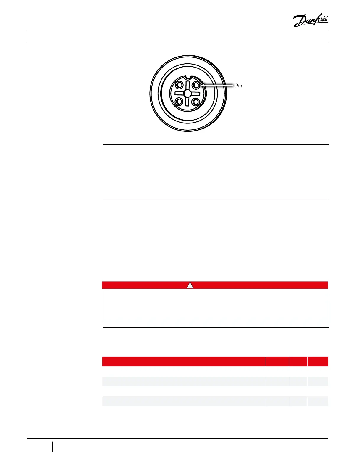
Figure 117 - PWM Connector
- 4 Pin
Pin 1
Compressor Components
Communication
1. Connect to the CCM using the SMT and enter the User ID and Access Code.
2. Open the Warnings and Faults Tool.
3. Verify that the CIM Compatibility, controller area network (CAN) Communications and VFD
Communications Faults are not active.
Calibration
A calibration should only be saved to EEPROM if there is a known bearing problem or when a new/
dierent Service Electronics Assembly is replaced.
1. Power on the Compressor.
2. Using the SMT, perform a compressor bearing calibration and save to EEPROM.
3. Select validation to test bearing levitation control.
4. Create and save a calibration report for records and review.
Description Nm Ft.Lb. In.Lb.
Power Cover, SHCS, M5x16 6 - 53
Service Side Cover, SHCS, M5x16 6 - 53
Power Cable Nut, Brass M10x1.5 10 8 89
Service Electronics Assembly fasteners 6 - 53
Service Electronics ground wires at left and 250 VDC ground wire at right 6 - 53
Table 26 - Electronics Side
Torque Specications
3.7.1.11.3 Torque
Specications
• • • CAUTION • • •
When replacing the Service Electronics Assembly, a bearing calibration must be performed and
saved to the EEPROM. The Service Electronics Assembly will then use the new values stored in
EEPROM to operate the compressor. Using default calibration data from a newly installed Service
Electronics Assembly to operate a compressor could cause erratic behavior.

 Loading...


