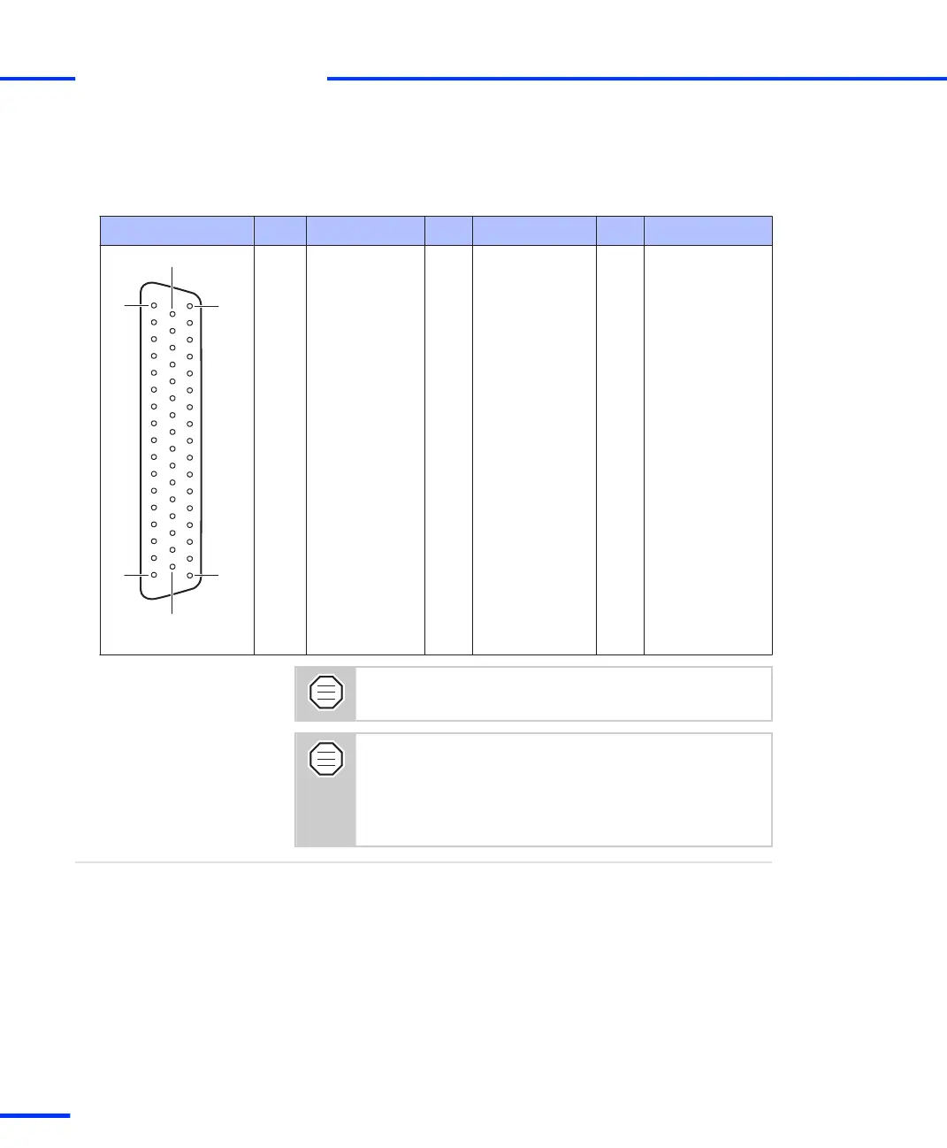
The table below shows the pin assignment of the Sub-D connector
P3B. Signal names in parentheses apply when the UART is set to the
RS422 mode.
Connector P3B Pin Signal Pin Signal Pin Signal
1 GND 34 TXD (TXD)
2 RTS (RTS) 18 RXD (RXD) 35 CTS (CTS)
3 STXD 19 RI (not used for
RS422)
36 SRXD
4 – 20 – 37 –
5 – 21 – 38 GND
6 PHI90(7) 22 PHI0(7) 39 IDX(7)
7 PHI0(6) 23 GND 40 PHI90(6)
8 GND 24 IDX(6) 41 PHI0(1)
9 IDX(1) 25 PHI90(1) 42 GND
10 PHI90(2) 26 PHI0(2) 43 IDX(2)
11 PHI0(3) 27 GND 44 PHI90(3)
12 GND 28 IDX(3) 45 PHI0(4)
13 IDX(4) 29 PHI90(4) 46 GND
14 PHI90(5) 30 PHI0(5) 47 IDX(5)
15 CANL 31 GND 48 CANH
16 VCC2 (+ 5 V) 32 GND 49 VCC2 (+ 5 V)
17 VCC3 (+ 5 V) 33 VCC3 (+ 5 V) 50 GND
The CAN bus lines (CANH, CANL) are not terminated with
a resistor on the DS1103.
The DS1103 provides three VCC lines. The total load of
every VCC line (VCC1, VCC2, VCC3) must not exceed 500
mA.
For details on the VCC lines refer to Power Supply Outputs
on page 162.
References
• Board Overview on page 105
• Power Supply Outputs on page 162
• Signal Connection to External Devices on page 161
Related topics
s
Connector Pinouts and LEDs
t
122
s
DS1103 Hardware Installation and Configuration November 2014