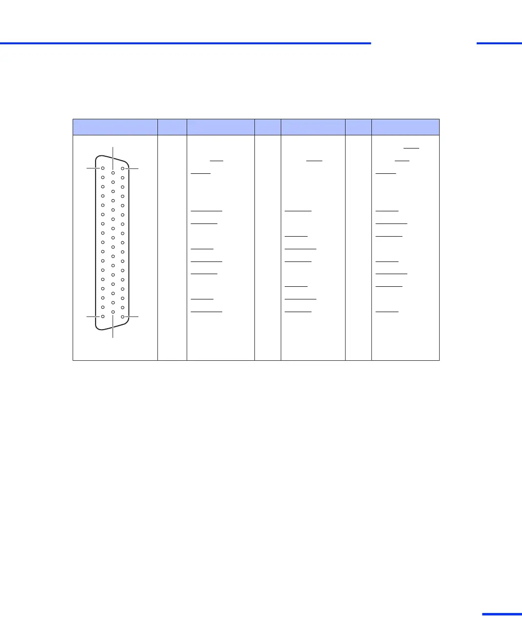
The table below shows the pin assignment of the Sub-D connector
P3A. Signal names in parentheses apply when the UART is set to the
RS422 mode.
Connector P3A Pin Signal Pin Signal Pin Signal
1 GND 34 Not used for
RS232 (TXD)
2 DTR (RTS) 18 DCD (RXD) 35 DSR (CTS)
3 STXD 19 GND 36 SRXD
4 – 20 – 37 –
5 – 21 – 38 GND
6 PHI90(7) 22 PHI0(7) 39 IDX(7)
7 PHI0(6) 23 GND 40 PHI90(6)
8 GND 24 IDX(6) 41 PHI0(1)
9 IDX(1) 25 PHI90(1) 42 GND
10 PHI90(2) 26 PHI0(2) 43 IDX(2)
11 PHI0(3) 27 GND 44 PHI90(3)
12 GND 28 IDX(3) 45 PHI0(4)
13 IDX(4) 29 PHI90(4) 46 GND
14 PHI90(5) 30 PHI0(5) 47 IDX(5)
15 GND 31 GND 48 GND
16 VCC2 (+ 5 V) 32 GND 49 VCC2 (+ 5 V)
17 VCC3 (+ 5 V) 33 VCC3 (+ 5 V) 50 GND
s
DS1103 Components
t
DS1103 Hardware Installation and Configuration November 2014
121
t