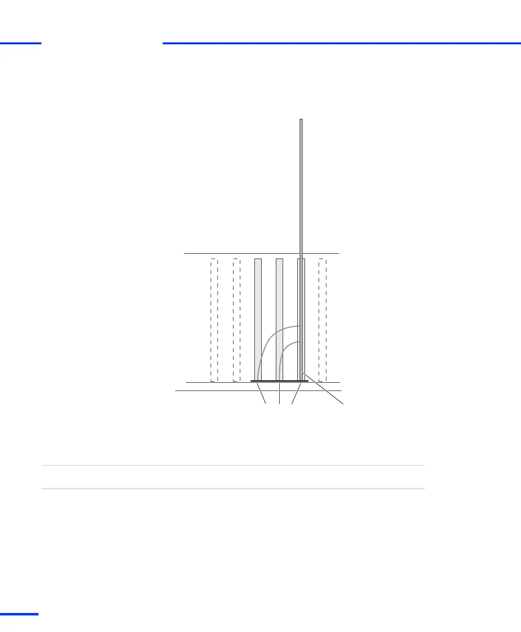
The connector next to the board is labeled P1, the second
connector is labeled P2 and the third one P3.
DS1103Triple connector bracket: P3, P2, P1
6 Close the enclosure.
7 Reconnect the PC, the expansion box and all connected devices to
the power supply.
The installation is complete.
Result
n If your system is installed in an expansion box, it must be
connected to your host PC via Ethernet or a bus interface. For
further information, refer to Connecting an Expansion Box to the
Host PC on page 53.
n You can switch on the dSPACE system. Refer to How to Switch On
the dSPACE System on page 41.
Next steps
s
Installing the Hardware
t
40
s
DS1103 Hardware Installation and Configuration November 2014