3GS Technical Manual
Issue 4.5 August 2005
8-68 Programming Menus
• Door/security barrier control
The Controller, RKD, and I/O module relays are normally OFF (de-energised) – that is, when the output is turned ON, the
relay is energised (except for Controller relay 1 which is fail safe and therefore normally ON, power removed, output OFF).
For this reason, output1 is Intruder Alarm and is used as the primary alarm indicator.
You can duplicate outputs in order to assign any number of I/O module relays the same number, in which case they will
respond identically.
For example, output 2 drives the 3GS Controller on-board relay to activate the external sounder and an I/O node output
could also be programmed as output 2 to trigger external security lights when the sounder operates. You assign outputs using
the Node Configure menu – see “Nodes Configure - Outputs” on page 8-32 for further information.
Note How an output operates is defined by the function assigned to it. More than one relay can be assigned to the same output
( i.e. more than one relay can be assigned to the same function)
Note For the DM1200 to initiate communications on activation of output 1, the unit must be programmed to view
this as a negative trigger. To do this, change the output trigger control from POS to NEG. See also DM1200 in 3GS
Peripherals.
Power Consumption
When a 1A relay energises, it can typically draw up to 30mA. It is important that you take into consideration this power
consumption when calculating PSU requirements, particularly if a 6-output node is in use where the current drawn by the
relays alone may exceed 180mA. Output devices such as sounders/strobes and so on will also be drawing large amounts of
current. Remote power supply units should be used to power I/O nodes in such a situation.
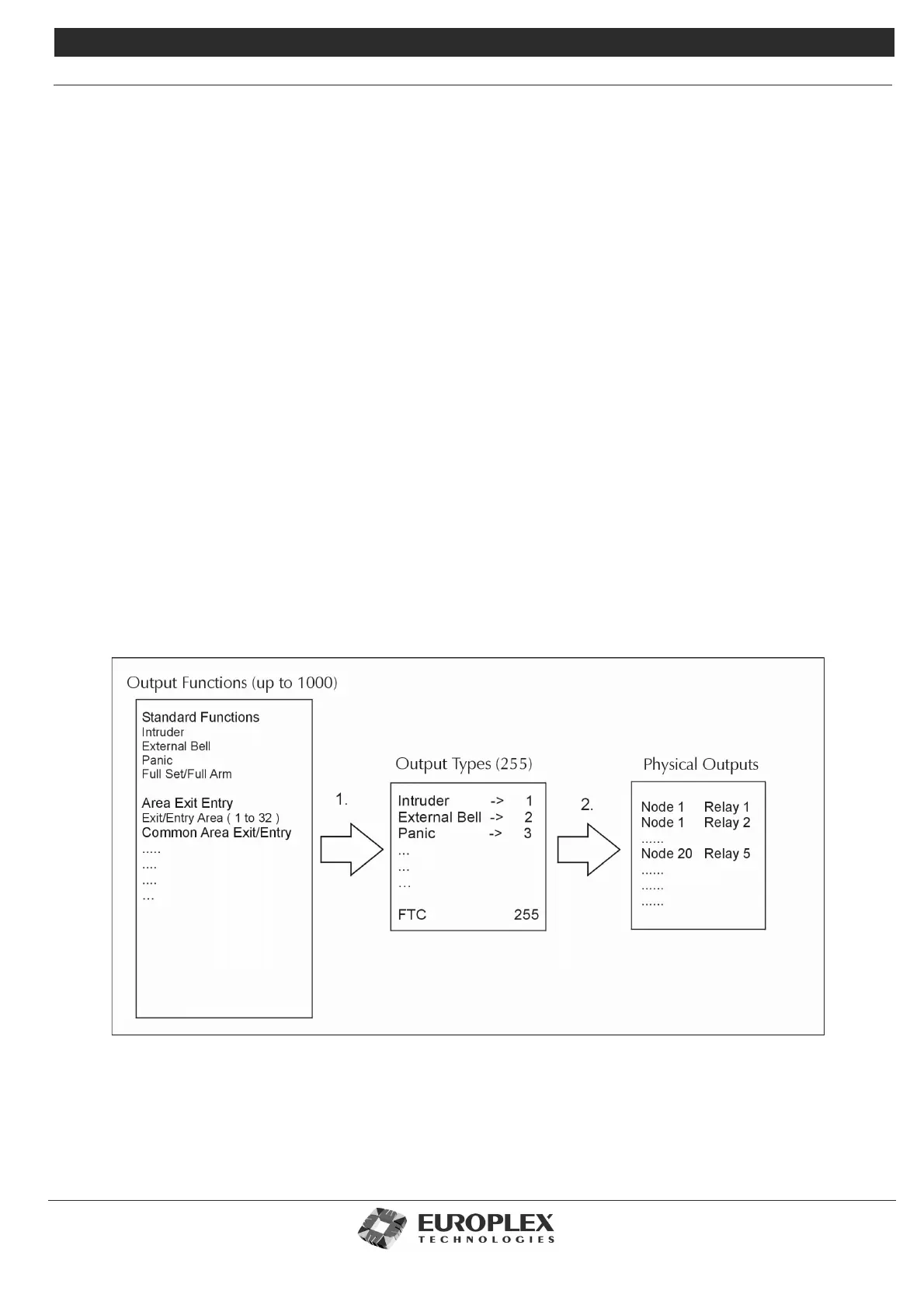
Output functions
Output types range from 1 to 255 with their pre-defined functions as shown below. Output functions range from 1 to 1000.
The 255 output types may be mapped to any of the 1000 output functions depending on the system requirements – see “Edit
Output Database” on page 8-84. The system allows for spare output types with no pre-defined function. For example: 110,
174, 175.
The 3GS Controller has 4 on-board 1Amp relays, defaulted to types 1, 2, 3, and 4, while relays on the Nodes are not
defaulted and can be addressed to any of 255 output numbers.
1. To assign Output functions to Output Types, the Edit Output Database programming option is used – see “Edit Output
Database” on page 8-84.
2. To assign Output types to Physical Outputs (Relays), the Node Configure - Outputs menu is used - see “Node Configure”
on page 8-26