Issue 4.5 Aug 2005 IntelliBell 14-3
INTELLIBELL OVERVIEW
Function
The IntelliBell (IB) has been specifically developed by
Europlex to interface with its 3GS controller. The IB
connects to the data line and monitors the state of the
control line to determine the state of its outputs.
The unit activates its piezo sirens and/or strobe when
certain pre-programmed panel outputs are triggered.
A second model of the unit is available which
incorporates a Voice Annunciator Board (VAB) and
Speaker as an alternative to the sirens. A pre-recorded
message is replayed on activation of the VAB.
The unit has one on-board zone and reports tamper
alarms, self-test failures, detected foam ingress, and
drilling using this zone.
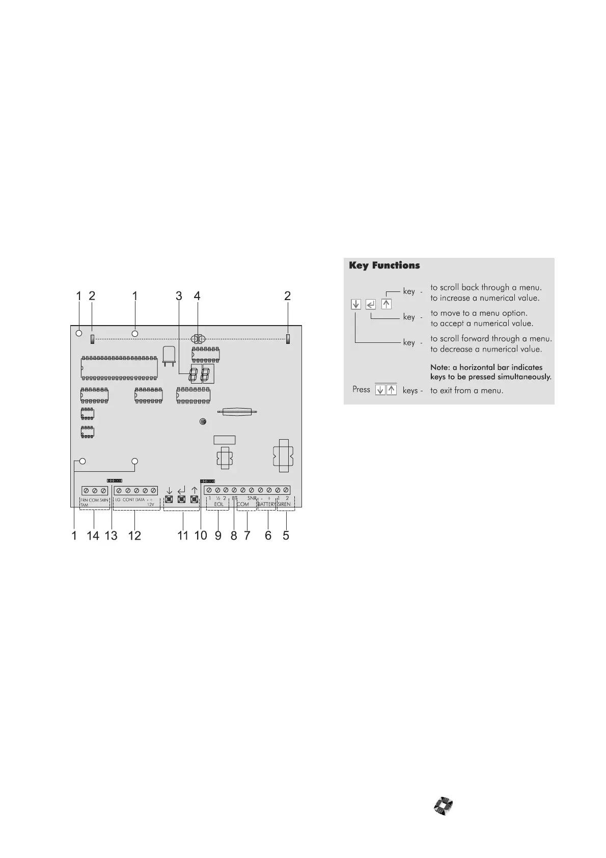
햲
Voice Annunciator Board (VAB) mounting holes -
The Sounder facilitates speech replay via an optional
add-on Voice Annunciator Board (VAB) and Speaker.
The speaker replaces the piezo sirens and both it
and the VAB are factory installed. The pre-recorded
message is stored in memory.
햳
Foam ingress detect receiver - To protect against
foam ingress, there are two infrared optical beams
on the board. If both beams are broken, a tamper
will be generated.
햴
Programming display - See “Programming” on page
4-4.
햵
Foam ingress detect transmitters - Use with the
foam ingress detect receivers.
햶
Sirens - See wiring diagram overleaf.
햷
Battery - See wiring diagram overleaf.
햸
Drill detect link - See wiring diagram overleaf.
The unit has a drilling detect feature whereby the
presence of drilling is reported to the panel. This fea-
ture may be enabled by removing a detect link and
connecting a mass inertia sensor.
햹
Back tamper - See wiring diagram overleaf.
햺
End-of-lines (EOLs) - See wiring diagram overleaf.
햻
Xenon tube and system active LED - See wiring dia-
gram overleaf.
햽
Programming keys.
햾
Data BUS - See wiring diagram overleaf. Feed all
external cables (Data line, DC power, and so on)
through the cable entry grommet in the cabinet.
Connect Data, Control, and Ground to the IB as
illustrated in the diagram overleaf. Secondary power
is supplied via a NiaCad battery pack. Connect the
battery pack leads (red: batt+, black: batt-) after pri-
mary power has been applied. The System Active
LED should blink to indicate the unit is functioning
correctly.
Note A maximum of 30m of alarm cable is
recommended between 3GS controller and IB. A higher
specification cable is recommended for distances
greater than 30m. LEM Ground should be connected to
COM at the 3GS Controller.
햿
VAB connector
헀
Front tamper and skin tamper - See wiring diagram
overleaf. There are two lever tamper switches on the
cabinet. If the double skin is punctured, a short
between both skins activates a tamper. An activation
of any tamper is reported to the panel using the on-
board zone. Remove the lid tamper switch transit
stop. Ensure that the tamper lever makes firm con-
tact with the wall when the unit is mounted.