Issue 4.5 August 2005 Nodes 5-53
WIRELESS NODE
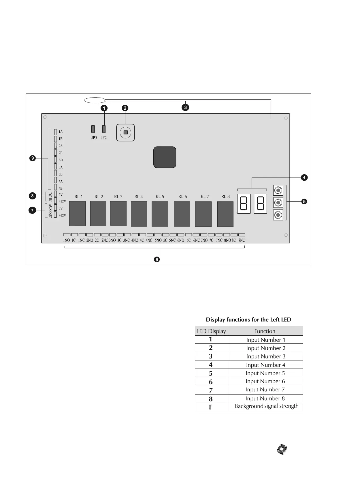
The 3GS Wireless Node provides an interface for up to 8 or 16 wireless detectors. The node incorporates 8 built-in relay
outputs, an easy to use programming interface consisting of two 7 segment displays and three push buttons, and a front
tamper switch.
햲
Tamper Jumper [JP2] This jumper setting deter-
mines the operation of the Tamper. To By-pass the
tamper, the jumper on JP2 is connected. With the
jumper on JP2 removed, the tamper is operational.
햳
Front Tamper Switch The Wireless node monitors
for front tamper
햴
Antenna The antenna is optimised for the 868/869
Mhz frequency band. Note - The 3GS wireless node is
supplied in two different variants. ( For use with
868MHz or 869MHz wireless detectors.)
햵
LED Programming indicators The wireless node
provides two 7 seven segment LED’s as a part of the
programming interface. These 2 LED’s combine to pro-
vide a visual indication of the state/properties of each
of the inputs.
The Left 7 segment LED of the programming
interface is used to display the input number
associated with a particular display function. This
LED is also used to indicate that the background
signal strength is being monitored.