Nodes 5-54
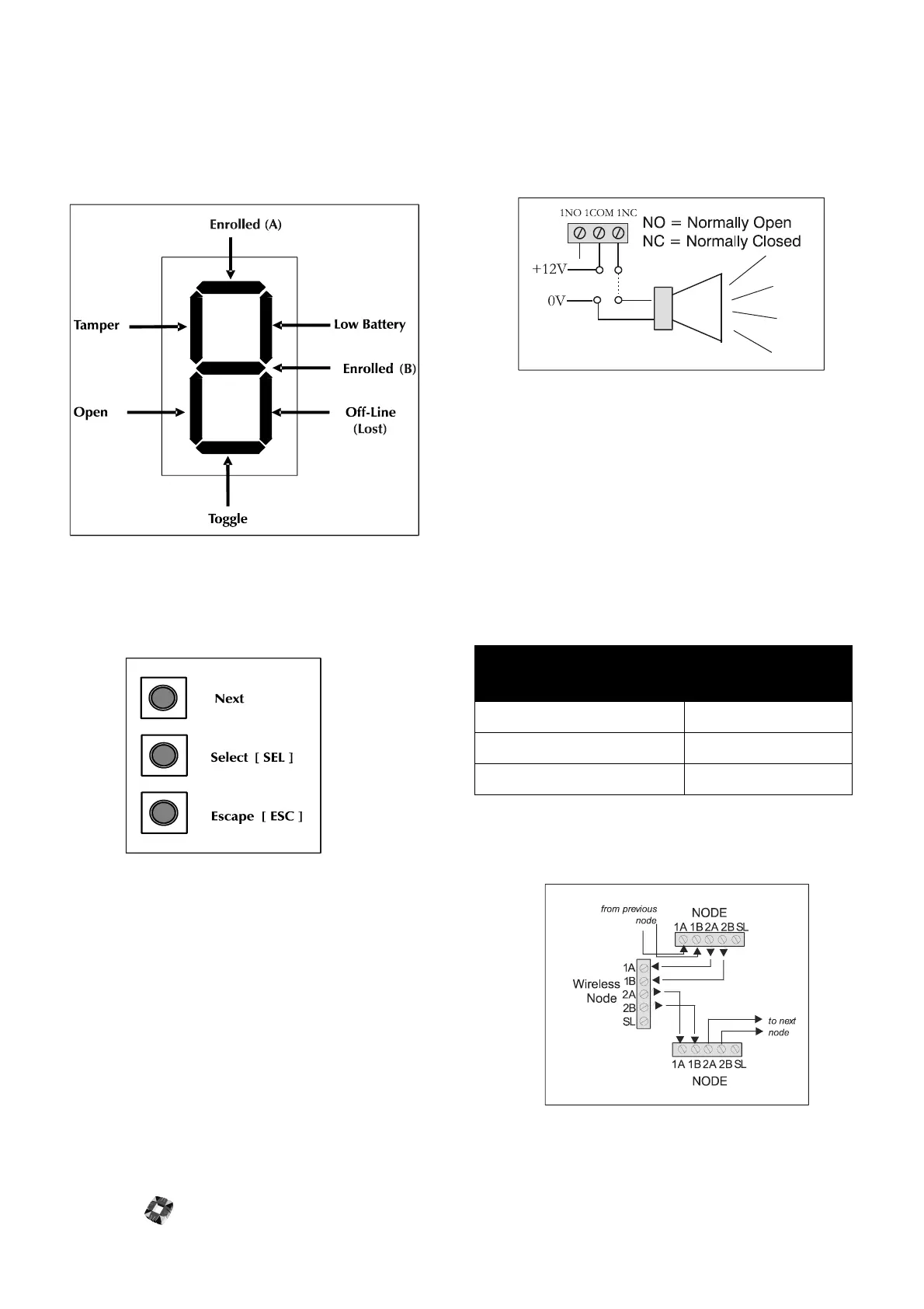
The Right 7 segment LED provides an indication of the
device status/properties. Each of the seven segments
corresponds to a particular state or condition as shown
below. The Horizontal segments indicate device Properties
while the vertical segments indicate device states.
햶
Programming Keys These 3 keys in combination
with the 2 LEDs provide the programming interface of
the wireless node.
The function of each of the 3 keys is listed below:
Select [SEL] Key: This key is used to select the required
display function. The user can circulate through each of the
available display functions by repeatedly pressing this key.
Next Key: This key is used to circulate through each of the
eight possible input devices for the selected display
function.
Note: not all of the display functions will have device
dependant properties, in these cases the Next key will have
no function.
Escape [ESC]:This key is used to exit the current function
and return to the normal operating state.
햷
Outputs The Wireless Node has eight on-board 1Amp
single pole changeover relays, which can be assigned to
any of the system outputs. See Node Configure->Out-
puts in 3GS Programming for further information.
햸
Auxiliary Power supply(12V) Used to power auxil-
iary devices to a maximum of 250mA.
햹
Input Power supply The Wireless Node requires
12V DC which should be supplied directly from control-
ler PSU or from a remote PSU.
햺
Ringnet Communications Connect the ringnet
cable to the four terminals 1A to 2B.These terminals are
used for connecting the wireless node onto the ringnet
– as illustrated in the following connection diagram and
cable type table.
cable type
maximum distance
between nodes
Belden 9502 (screened) 500m
UTP Category: 5 solid core 1000m
Belden 9829 1000m