Nodes 5-50
ENCRYPTION NODE
Description
The traditional method of detecting alarm and tamper inputs uses end-of-line resistance, where different resistance
values reported to the panel will indicate different states. The 3GS Encryption node receives encrypted inputs from an
encryption module placed inside the alarm sensor. The node is wired for both alarm and tamper loops and has an
individual node address. In this way, the panel receives alarm or tamper events from an individual zone input address,
making system compromise more difficult. The node also incorporates all the features of the 3GS 8 Input/1 Output
node – see page 5-13 for further information.
햲
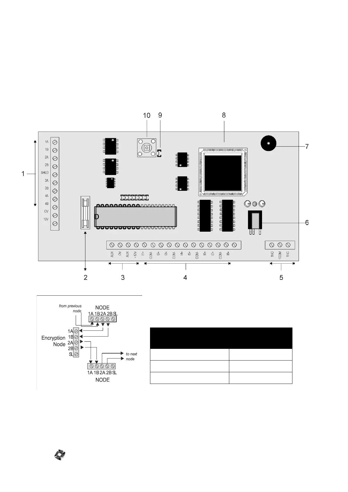
Ringnet Communications Connect the ringnet cable to the
four terminals 1A to 2B.
These terminals are used for connecting
the encryption node onto the ringnet – as illustrated in the follow-
ing connection diagram and cable type table.
Note See the branch node diagram in the following section: “8 Input/1 Output (I/O) Node” on page 5-13.
햳
Auxiliary supply fuse 250mA Quick Blow.
햴
Auxiliary supply (12V) Used to power auxiliary devices to a maximum of 250mA.
햵
Inputs The Encryption node has eight on-board zone inputs. These inputs are monitored using dual EOL
cable type
maximum distance
between nodes
Belden 9502 (screened) 500m
UTP Category: 5 solid core 1000m
Belden 9829 1000m