Issue 4.5 Aug 2005 Network Router 13-5
Note The diagram on page 13-4 illustrates a typical connection of multiple 3GS Controllers (remote and local)
via the network router to a PC.
Connecting Local or Remote PC
The network router has both an RS232 and RS422 Master Input. This enables a local PC to be directly connected to
the Network Router via the RS232 Master Input. Alternatively, the Network Router can be placed up to 1.6 kilometres
away from the controlling PC and connected via the RS422 Master Input.
● To connect a local PC to the network router over RS232, a standard PC serial cable is used. This cable is provided.
● To connect a remote PC over RS422 to a Network Router, a LDAC (or another Network Router) is required beside
the PC to convert to RS422.
● You cannot connect both an RS232 and RS422 Master Input at the same time.
Connecting Network Router to Remote PC Via LDAC
Note you will need to patch from 9A-B and 2A-7B on the LDAC to convert from RS422 back to RS232 for the
PC. A similar configuration can be used on the 3GS controller side. Connect from one of the network router slave
RJ45 outputs to the LDAC. Then connect from the LDAC to the 3GS serial port.
Connecting to RS232 Devices (Local 3GS/Via Modem)
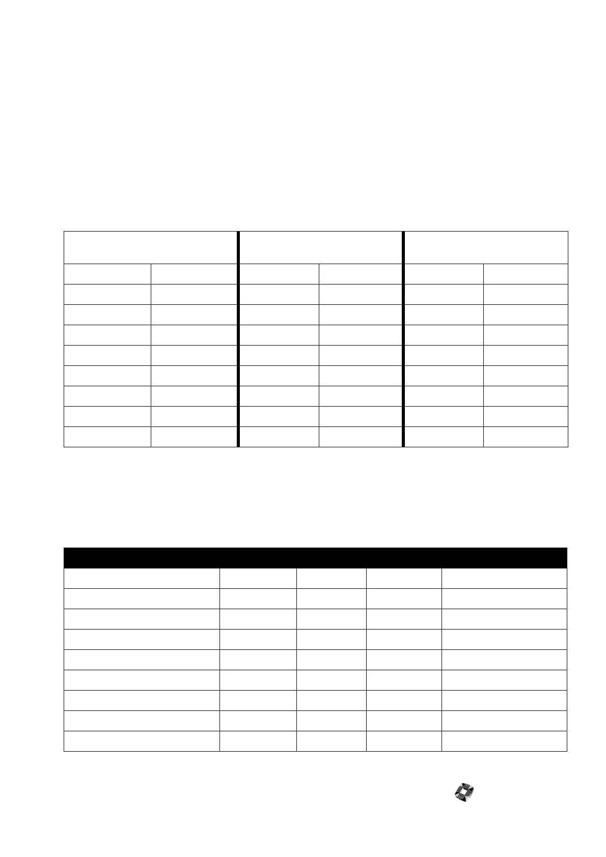
The following table displays the wiring details on how to connect a Network Router to a modem or 3GS.
NETWORK ROUTER
REMOTE MASTER INPUT (RJ45)
LDAC IN RS422 LDAC OUT RS232 TO PC
Cable colour PIN Number PIN Number Signal Name PIN Number Signal Name
Blue/White 1 1 A/RX
Blue 2 2 B/RX
Brown/White 3 B-
Brown 4 8 RX
Orange/White 5 10 TX
Orange 6 B- 11 GROUND
Green/White 7 13 A/TX
Green 8 14 B/TX
NETWORK ROUTER SIDE (RJ45) 3GS MODEM CONNECTIONS
Channel 1-8 Cable Colour PIN Number Port 1 Port 2/Port 3 Modem 25 Pin D-Type
Blue/White 1TX Positive
Blue 2 TX Negative
Brown/White 3 0V 7 GND 0V 7 GND
Brown 4 TX 2 RX IN RX 3 RX
Orange/White 5 RX 3 TX OUT TX 2 TX
Orange 6 0V 7 GND 0V 7 GND
Green/White 7 RX Positive
Green 8 RX Negative