Issue 04 October 2004 Intelligent PSUs 4-5
Additional Information
Connecting the Intellipower PSUs
In order to function as specified, both primary and secondary power sources should be connected to the 3GS PSU. The
PSU features temperature compensated battery charging. It also has an on-board resistor to enable testing of the
battery. The PSU has three independent fused outputs.
The primary power source is connected to the PSU via a fused mains block, CN1, which is located on the extreme left
of the PCB. The mains supply should also have a good earth which must be connected to the mains block so labelled.
In the event of a mains failure, it is essential to have a battery backup as a secondary power source. We recommend
using the Yuasa NP series of batteries. Connect a sealed 12V lead-acid battery to the battery pos/neg terminals (7) as
illustrated in the diagram – “PSU 4/6 Amp” on page 3-4.
The PSU delivers 13.65VDC to the controller PCB via a 14 way ribbon cable (13) – also illustrated in diagram, “PSU 4/
6 Amp” on page 3-4. Monitored data (such as low battery, fuse fail, mains fail) is also carried on this cable.
Standby battery
Ensure that adequate standby power is available for all devices in the event of mains supply failure. The capacity of the
battery is expressed as a standard ampere hour rate by multiplying the current drawn and the time taken before the
battery terminal voltage falls to a set figure.
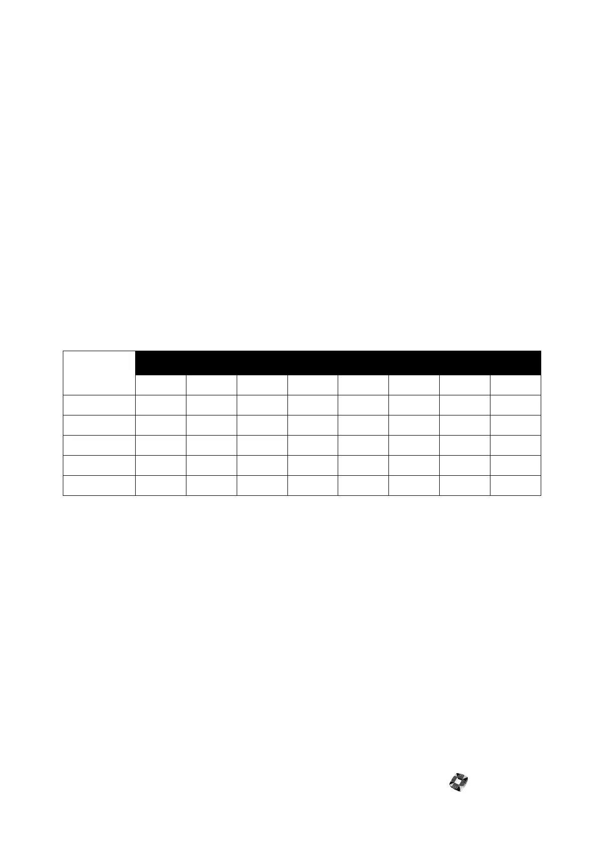
Use the following table to calculate the power requirement. For example, if you have a 3Amp load and require 16
hours standby battery backup, you need a 48Ah battery (2x24Ah) with the 6Amp version of the PSU. The following
table has been calculated on the basis of a battery recharge time of 24 hours – that is, in 24 hours, the battery is
recharged to 80% of its normal capacity.
To check the battery on a 4/6Amp PSU
1 The system should be initially powered up on the standby battery.
2 Ensure a 12V rechargeable battery is connected and then hold down the controller Kick Start button for
approximately five seconds.
This should energise Relay A and power the system from the standby battery (assuming the battery voltage is above
10.5VDC) .
The yellow LED on the PSU should illuminate indicating that a charged battery is connected.
3 Apply the AC mains voltage to the PSU.
The green LED located beside the mains terminal should illuminate to indicate mains voltage is present. Battery
charging is controlled by the 3GS controller. When the battery charge relay closes, the yellow LED illuminates to
indicate the battery is being charged.
Class IV SEAP System
The Class IV SEAP system requires 30 hours of battery backup. The battery should be recharged in 24 hours. Therefore
to deliver 1 Amp, a 30 Ah battery is required. We recommend that a single battery be used for battery backup on
the Class IV system.
Currently, Class IV systems for the UK market only require 24 hour backup on the battery.
Load
1 Amp 2 Amp 3 Amp 4 Amp
Standby time Battery PSU Battery PSU Battery PSU Battery PSU
12 hours 12Ah 4A 24Ah 4A 36Ah 6A 48Ah 6A
16 hours 16Ah 4A 32Ah 6A 48Ah 6A 64Ah 6A
24 hours 24Ah 4A 48Ah 6A 72Ah 6A
60 hours 60Ah 6A
72 hours 72Ah 6A