DMP 128 FlexPlus • Remote Control and Configuration 124
RS-232 Port
The DMP 128 FlexPlus has a serial port that can be connected to a host device such as
a computer running either the DataViewer or HyperTerminal utilities. The port makes serial
control of the DMP 128 FlexPlus possible.
The DMP 128 FlexPlus uses the following RS-232 protocols:
• 38400 baud • No parity • 1 stop bit
• 8 data bits • No flow control
NOTES:
• The rear panel configuration port requires 38400 baud communication. This
speed is higher than most other Extron products. The DMP 128 FlexPlus control
software automatically sets the connection for the appropriate speed. When using
DataViewer or similar application, make sure the host PC or control system is set
for 38400 baud.
• See Rear Panel Features and Cabling on page4 for additional details on
connecting to the RS-232 port.
LAN Port
The DMP 128 FlexPlus can be connected to an Ethernet LAN or WAN. Communication
between the device and the controlling device is via Telnet (a TCP socket using port 23). The
Telnet port can be changed, if necessary, via SIS. This connection makes SIS control of the
device possible using a computer connected to the same LAN or WAN. The SIS commands
and behavior are identical to the commands and behavior the product exhibits when
communicating by serial port or USB.
The DMP 128 FlexPlus LAN (LAN 1 on V-model) port defaults are as follows:
IP Address Subnet Mask Default Gateway DHCP
192.168.254.254 255.255.255.0 0.0.0.0 OFF
The Ethernet cable can be terminated as a straight-through cable or a crossover cable and
must be properly terminated for your application.
• Crossover cable — Direct connection between the computer and the DMP 128
FlexPlus.
• Straight-through (Patch) cable — Connection of the DMP 128 FlexPlus to an
Ethernet LAN.
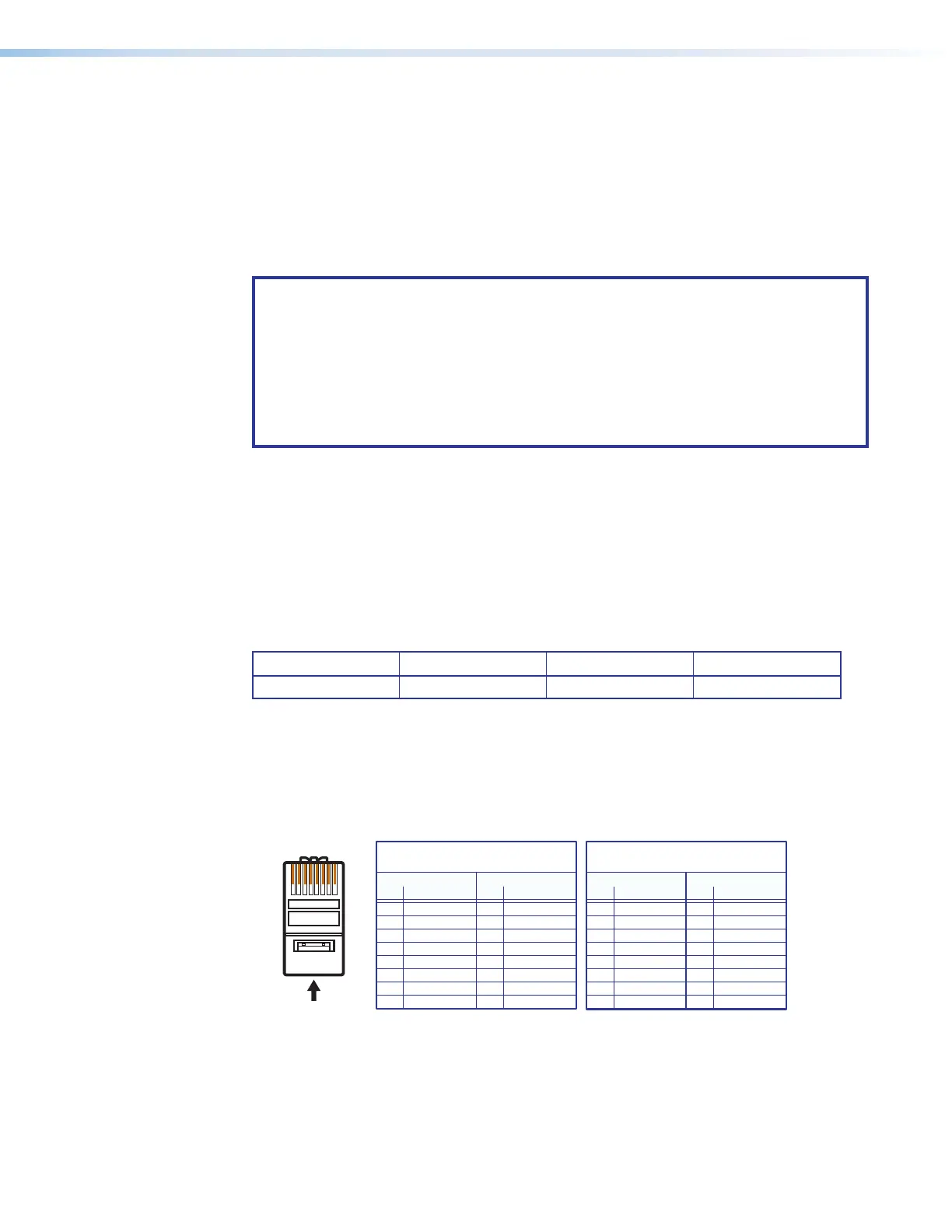
12345678
RJ-45
Connector
Insert Twisted
Pair Wires
Pins:
A cable that is wired as TIA/EIA T568A at one
end and T568B at the other (Tx and Rx pairs
reversed) is a "crossover" cable.
A cable wired the same at both ends is called
a "straight-through" cable because no pin/pair
assignments are swapped.
T568A T568B T568B T568B
Straight-through Cable
(for connection to a switch, hub, or router)
End 1 End 2
Pin Wire Color Pin Wire Color
1 white-orange 1 white-orange
2 orange 2 orange
3 white-green 3 white-green
4 blue 4 blue
5 white-blue 5 white-blue
6 green 6 green
7 white-brown 7 white-brown
8 brown 8 brown
Crossover Cable
(for direct connection to a PC)
End 1 End 2
Pin Wire Color Pin Wire Color
1 white-orange 1 white-green
2 orange 2 green
3 white-green 3 white-orange
4 blue 4 blue
5 white-blue 5 white-blue
6 green 6 orange
7 white-brown 7 white-brown
8 brown 8 brown
Figure 188. RJ-45 Ethernet Connector Pin Assignments
figure 178. RRJ-45