DMP 128 FlexPlus • Dante Controller 116
Physical Dante Network Setup
A physical network is required to share Dante audio channels between Dante-enabled
devices like the DMP 128 FlexPlus. Other Dante-enabled devices must be on the same
physical network in order to communicate via Dante. A daisy chain topology can be used to
connect multiple devices.
Daisy Chain topology has DMP 128 FlexPlus units connected in succession.
POWER
12V
2.0 A MAX
1
2
3
4
1
2
5
6
7
8
1 (PRI)
C V A T
1
2
RS-232
R
Tx Rx G
+V +S -S G
DMP EXP
AT
ACP
LAN/VoIP
USB AUD
INPUTS
1
2
3
4
2 (SEC)
I/O
OUTS
REMOTE
IN G O IN G O
POWER
12V
2.0 A MAX
1
2
3
4
1
2
5
6
7
8
1 (PRI)
C V A T
1
2
RS-232
R
Tx Rx G
+V +S -S G
DMP EXP
AT
ACP
LAN/VoIP
USB AUD
INPUTS
1
2
3
4
2 (SEC)
I/O
OUTS
REMOTE
IN G O IN G O
POWER
12V
2.0 A MAX
1
2
3
4
1
2
5
6
7
8
1 (PRI)
C V A T
1
2
RS-232
R
Tx Rx G
+V +S -S G
DMP EXP
AT
ACP
LAN/VoIP
USB AUD
INPUTS
1
2
3
4
2 (SEC)
I/O
OUTS
REMOTE
IN G O IN G O
POWER
12V
2.0 A MAX
1
2
3
4
1
2
5
6
7
1 (PRI)
1
2
RS-232
Tx Rx G
+V +S -S G
DMP EXP
AT
ACP
LAN/VoIP
USB AUD
INPUTS
1
2
3
4
2 (SEC)
I/O
REMOTE
IN G O IN G O
Ethernet
Figure 180. Daisy Chain Network Topology
NOTE: The daisy chain topology only functions in switched mode. It is not possible to
use in redundant mode.
Redundant Configuration
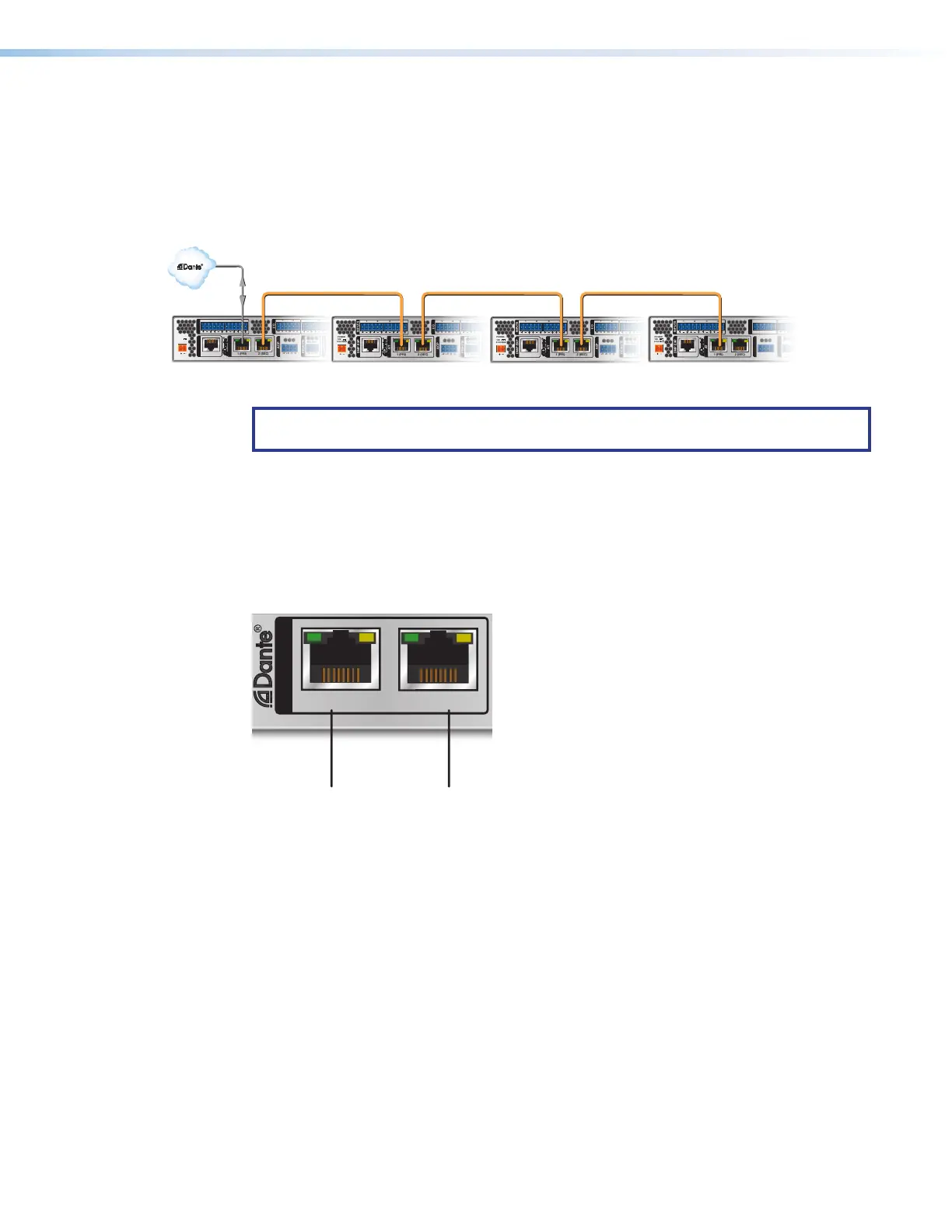
In redundant mode, the 2-port AT switch becomes separate primary and secondary ports
that duplicate audio traffic. Port 1 is marked (PRI) for primary while port 2 is marked
(SEC) for secondary (see figure 181 below). Primary and secondary switches/ports cannot
be connected together anywhere in the audio network. Redundant configuration can be
enabled using Dante Controller or DSP Configurator.
POWER
12V
2.0 A MAX
1
2
3
4
1
2
5
6
7
8
1 (PRI)
C V A T
1
2
RS-232
R
Tx Rx G
+V +S -S G
DMP EXP
AT
ACP
LAN/VoIP
USB AUD
INPUTS
1
2
3
4
2 (SEC)
I/O
OUTS
REMOTE
IN G O IN G O
Primary Port
Secondary Port
Figure 181. Primary and Secondary AT Ports
170 Physical Dante Network Diagram
171 Primary and Secondary Ports