122
Program description - Control adjust | Helicopter models
Conversely, the throttle servo or speed controller can
only open up to its full-throttle position if the throttle
limit control has also released the full servo travel path.
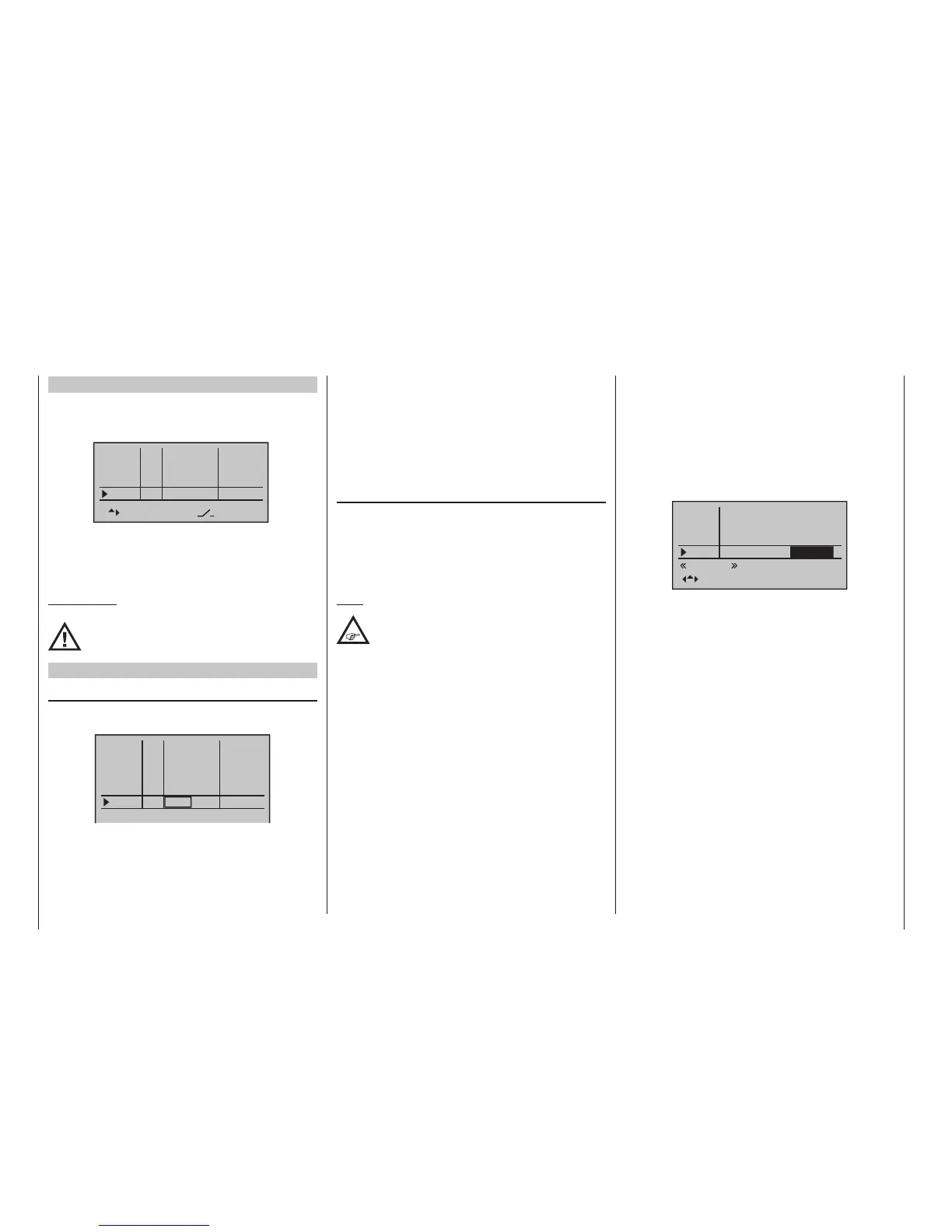
The value set on the (right-hand) plus side of the “trav-
el” column must therefore always be set high enough
to ensure that the maximum setting of the throttle limit
control never restricts the full-throttle position achiev-
able with throttle curve settings – which typically means
setting a value in the range +100 % to 125 %.
– travel +
+100%
+100%
+100%
Gyro
Lim.
+100%
+100%
+100%
+100%
normal
+125%
In5
Thro
The value on the (left-hand) minus side of the “travel”
column should be set so that the throttle limit control
can safely cut off an electric drive or close a carburettor
sufficiently to cut off a combustion motor in conjunction
with – digital – C1 trim. Because of this, leave this value
(initially) at +100 %.
Furthermore, this variable “limitation” of throttle travel
not only provides a convenient means to start and stop
the motor but may also prove to be more than an insig-
nificant safety improvement! For example, just imagine
what could happen if, while carrying the helicopter to
the take-off site with the motor running, the C1 stick
were to be inadvertently operated …
Firmware version V1103 and higher
From this firmware version if the input is “Lim.” after
initializing a new model memory with the model type
“Helicopter” is by default “free”:
Gas
offset
Gyro
In8
–––
–––
–––
0%
0%
0%
GL
GL
GL
typ
fr
fr
fr
SEL
–––
0%
GL
fr
Lim
However, by assigning a switch, for example, the
above default assigned right side proportional slider
SD2 described below option “Throttle limit” can be re-
activated at any time and adjusted as described below.
ATTENTION:
The throttle limiter only remains disabled as
long as the input “Lim” is free! Otherwise this
input cannot be used.
Firmware version V1102 and lower
“Lim.”
The proportional slider Lv2, mounted on the right side
of the transmitter, is assigned by default to input “Lim.”:
In5
–––
0%
GL
fr
In8
This pre-assignment makes it unnecessary to program
the two flight phases as may be familiar from use of
other remote control systems – one “with idle-up” and
Throttle limit function
one “without idle-up” – because the given options of the
transmitters mc-16 HoTT and mc-20 HoTT offers
a much more flexible approach to fine-tuning and opti-
mizing increases to system rotational speed below the
hover point than the so-called “idle-up”. If it is never-
theless preferable for the helicopter to be programmed
“with idle-up”, then deactivate the “throttle limit” func-
tion described below by setting input “Lim.” to “fr”.
Meaning and application of “throttle limit”
As already mentioned under “Throttle”, and in contrast
to fixed-wing models, the power output of a helicop-
ter’s drive system is not controlled directly with the C1
stick, but only indirectly via the throttle curve settings in
the »Helicopter mixer« menu or – if the model features
a speed controller – via that mechanism.
Note:
Of course for different ight phases, ight
phase programming can be used to set
individual throttle curves.
Nevertheless, both methods of output control de facto
result in the helicopter carburettor never approach-
ing anything near its idle speed under “normal” flight
conditions, and that the motor can therefore neither be
started or stopped cleanly without some other means
of intervention.
The “throttle limit” feature resolves this problem ele-
gantly by using a separate transmitter control – by
default the Lv2 proportional slider mounted on the right
side of the transmitter – to limit the throttle servo or the
output level of a speed controller. In this way, it is pos-
sible to “throttle back” with the throttle limit control,
even as far as the idle setting, at which point the trim
control for the throttle/pitch stick takes over or directly
shuts off an electric drive.

 Loading...


