172
Program description - Wing mixers
Values in the range -150 % to +150 % are possible, so
as to adjust the function to the direction of servo rota-
tion or direction of elevator movement.
A simultaneous tap on the or keys of the right
four-way button (CLEAR) will reset a changed value in
a given active (inverse video) field back to 0 %.
If required, the mixer can be switched on or off by as-
signing a switch in the right column.
The values configured for this mixer are typi-
cally in the single-digit range.
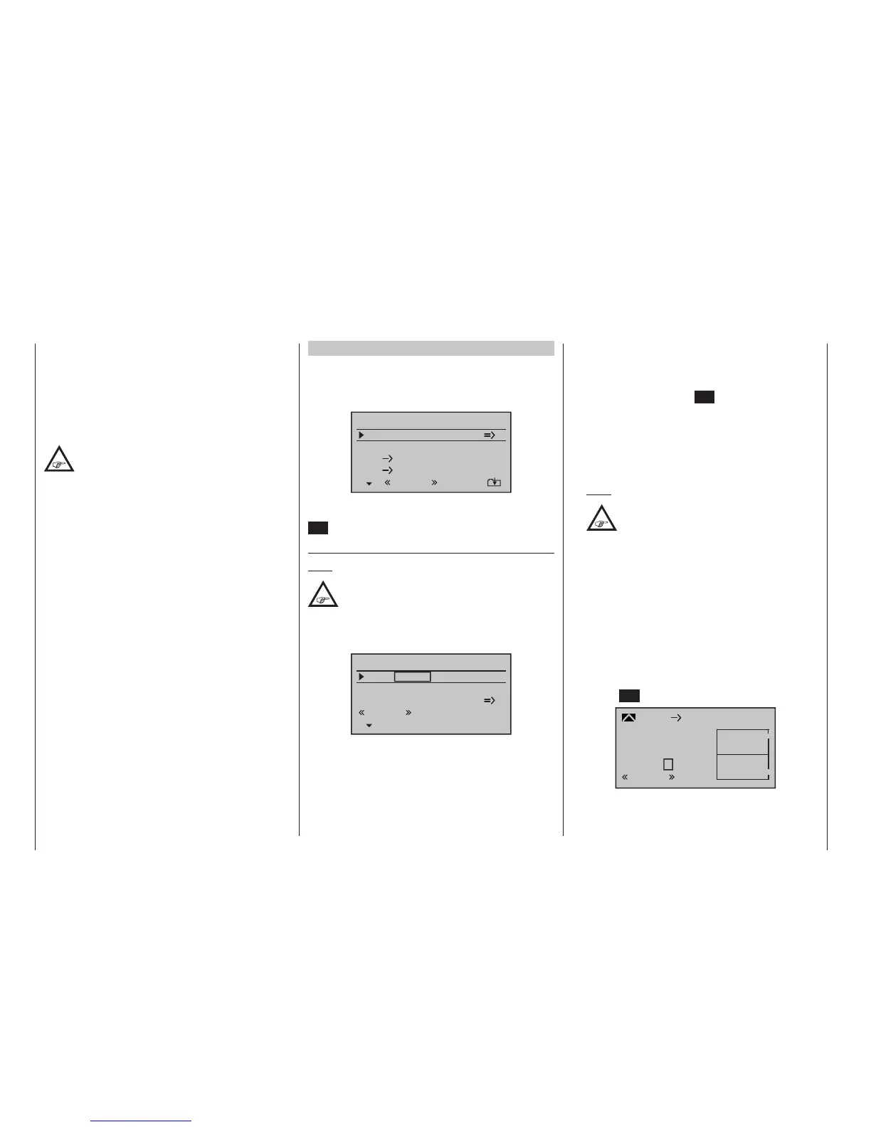
Model type: “2AIL”
If you have entered “2AIL” for the “Aileron/camber
flaps” line on the »Model type« menu, page 98, then
the “Wing mixers menu” on your transmitter will match
the following screen image:
Aile.diff.
Brake settings
0%
AI
0%
Wing mixers
EL AI 0%0%
–––
–––
RU
normal
From the first line on this display screen, you can
switch to the sub-menu with a brief tap on the centre
SET key of the right four-way button…
Brake settings
Note:
The “Brake settings” menu is switched “off” if:
“Motor on C1 forward / back” in the »Model
type« menu, page 98, AND the “Motor”
column of the »Phase settings« menu, page 148,
are set to “yes” for the currently active ight phase.
Switch the ight phase if required:
Elevat curve
Brake settings
AILE
Crow
D.red
0%
0%
0%
0%
0%
0%
WK WK2
normal
Depending on the model type selected, setting options
will now be available in the “Crow” and “D(ifferential)
red(uction)” lines for the column labelled “AILE”.
These options should be utilized by …
• … putting the transmitter control for “Brake” (re-
ferto the »Model type« menu description on
page98) – typically the C1 stick – in its limit posi-
tion in the brake direction. Switch to the “Crow” line,
briefly tap on the centre SET key of the right four-
way button and use the selection keys on the left
or right four-way button to set a value that moves
the aileron upwards as far as possible to brake the
model or, if you are using airbrakes as the main
braking system, the aileron should be set to elevate
only minimally to provide an extra braking effect.
Note:
To reliably prevent the servos mechani-
cally striking their end-stops – which draws
a heavy current – you can set an appropri-
ate limit value in the column labelled “– limit +” in
the »Servo adjustment« menu, page 106.
• … then finally, moving to the “D.red” line, set a %
value there which is greater than or equal to that
value set (or to be set) in the “Aileron differential” line
of the display screen “before” this one.
In this way, you can suppress the aileron differential
when braking, thus ensuring that you can count on
sufficient aileron response despite your ailerons be-
ing deflected upwards.
From the lowest line, “Elevator curve”, you can switch
to setting the “Elevator curve” mixer by briefly tapping
the centre SET key of the right four-way button:
Input
Output
Point
?
–100%
0%
0%
Brake
normal
Ele
Curve
off
normal

 Loading...


