112
Program description - Control adjust | Winged models
Control adjust
Basic procedure for transmitter control and switch assignment
This option is available on both transmit-
ter types.
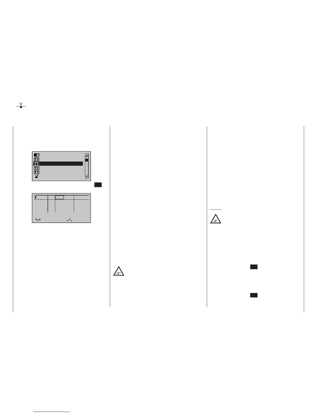
Use the selection keys on the left or right
four-way button to scroll to the »Control
adjust« option in the multi-function menu:
Servo adjustment
Dual Rate / Expo
Stick mode
Channel 1 curve
Switch display
Control adjust
Open this menu option with a tap on the centre SET
key of the four-way button pad:
In5
offset
0%
0%
0%
–––
0%
In6
In7
In8
–––
–––
–––
GL
GL
GL
GL
typ
normal
fr
fr
fr
fr
SEL
Although the basic hardware features of the mc-16
HoTT and mc-20 HoTT transmitters are the same,
i. e. two dual-axis sticks for control functions 1 to 4 and
the associated trim levers, the standard supplementary
controls fitted to the two transmitters are different.
•
mc-16 HoTT
• two 3-way switches (SW 5/6 & 11/12)
• two proportional sliders on the middle console,
designated Sl 1 & 2 in the menu
• two side-mounted “rotary sliders”, designated
Lv1 and 2 in the menu
•
mc-20 HoTT
• three 3-way switches (SW 2/3, 5/6 & 11/12)
• five 2-way switches (SW 4, 7, 9, 13 & 15)
• two self-restoring 2-way switches (SW 8 & 14)
• two unlockable 2-way switches (SW 1 & 10)
• two push-buttons on the back-side of the trans-
mitter (SW 16 & 17 bzw. 18 & 19)
• two switch-keys (Gb5 & Gb6)
• two proportional sliders on the middle console,
designated Sl 1 & 2 in the menu
• two side-mounted “rotary sliders”, designated
Lv1 and 2 in the menu
In contrast to the two sticks which, when initialized for
a new model memory as a “Winged aircraft” model
type will already be configured to operate the servos
connected to receiver outputs 1 … 4, these “other”
operating elements initially remain inactive.
Thus, at least in the system’s delivered state – as al-
ready mentioned on page 70 – or even after initializa-
tion of a new model memory with an “aircraft” model
type and its “binding” to the receiver intended for instal-
lation, only those servos connected to the two sticks
by way of receiver outputs 1 … 4 are able to be oper-
ated; any servos which may be connected to receiver
outputs 5 and upper will initially remain inactive in their
middle positions.
While this may appear a bit awkward at first glance …
this is the only way to ensure a completely free selec-
tion from among “additional” operating elements while,
at the same time, not requiring the “deactivation” of
unused operating elements.
This is because:
The only way to ensure an unused operat-
ing element can have no effect on the
model, even if operated by accident, is to
make it inactive, i. e. not assigned to any function.
All of the aforementioned operating elements can be
freely assigned in this »Control adjust« menu to any
function input, see page 58, just to accommodate
personal requirements. Equally, this also means that
each of these operating elements can also be assigned
to multiple functions at the same time, as needed. For
example: the exact same toggle switch assigned to
an input in this menu can, at the same time, also have
an assignment in the »Timers (general)« menu as an
“On/Off” switch, etc.
Furthermore, all inputs can be selectively set to global
or ight-phase specic operation if they have been de-
fined for flight-phases in the »Phase settings« menu,
page 148, and »Phase assignment« menu, page
154. The names assigned to given flight phases then
appear in the second-from-the-bottom display line,
e. g. «Normal».
Notes:
In contrast to servo travel the control travel
setting affects all outgoing mixer and coupling
functions, and thus all servos which are oper-
ated via the relevant operating element.
Basic procedure
1. Use the selection keys of the left or right four-
way button to select the desired input, “In5 … In8”
or “In5 … In12”.
2. If necessary, use the selection keys of the left
or right four-way button to change to the desired
column.
3. Briefly tap the centre SET key of the right four-way
button. The corresponding input field is shown high-
lighted.
4. Operate the chosen operating element or set the
desired value with the selection keys of the right
four-way button.
5. Briefly tap the centre SET key of the right four-way
button to complete data entry.
6. A simultaneous tap on the or keys of the
mc
16 20

 Loading...


