113
Program description - Control adjust | Winged models
right four-way button (CLEAR) will any setting made
back to its respective default value.
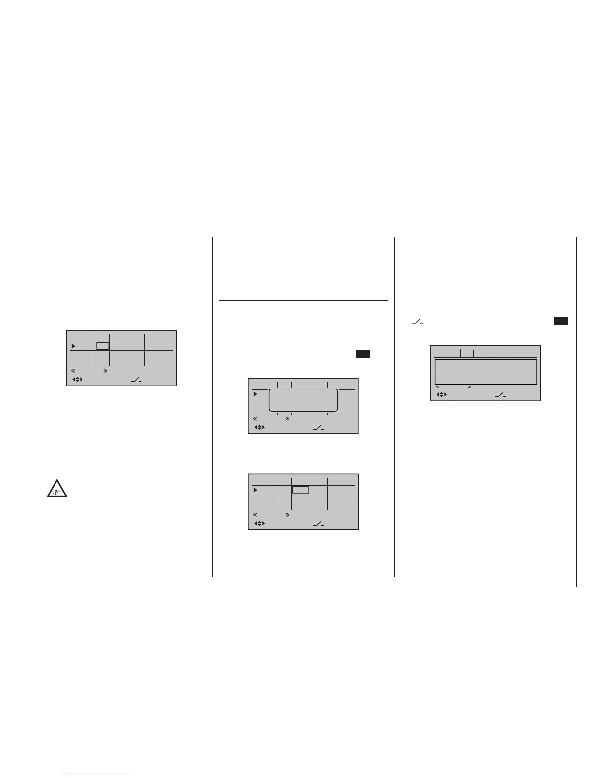
Column 2, “Typ”
Similar to the previously described »Stick mode«
menu, this column can be used to define whether fur-
ther settings for the given input are to have a “GL(obal)”
or a “PH(ase-specific)” effect. Do this by using the
selection keys of the left or right four-way button to
select the desired input 5 through 8 or 5 through 12 in
the column labelled “Typ”, for example:
0%
0%
0%
–––
0%
–––
–––
–––
GL
GL
GL
GL
normal
fr
fr
fr
fr
SEL
In5
offset
In6
In7
In8
typ
• “GL(obal)“
The settings for the input in question affect all flight
phases programmed (if any) and thus act “globally”
on the model memory in question.
• “PH(ase)”
The settings for this input take effect per flight
phase and must therefore be configured separately
for each flight phase.
Notes:
•
The current positions of the INC/DEC but-
tons CTL 5 & 6, which are generally as-
signed to inputs 5 … 8 or 5 … 12, are
stored in accordance with your chosen entry in the
“Type” line, i. e. the settings are not lost when you
switch ight phases or change models.
The particular advantage of these two transmitter
controls – especially if you select the “PH” setting -
lies in the fact that you can use one and the same
INC/DEC button as trim controls in all the pro-
grammed ight phases,
but – in contrast to a position-related proportion-
al control – the trim values are retained even if you
switch models.
• See page 146 for more information about ight
phases.
Column 3,
“Transmitter control and switch assignment”
Select an input, 5 through 12 max., with the selec-
tion keys of the left or right four-way button.
Transmitter control assignment
Use the selection keys to move into the column la-
belled SEL. After completing the activation of transmit-
ter control assignment by tapping the centre SET key
of the right four-way button, the message shown below
will appear in the display:
0%
0%
0%
–––
0%
–––
–––
–––
GL
GL
GL
GL
normal
fr
fr
fr
fr
SEL
In5
offset
In6
In7
In8
typ
Move desired
control adj.
Now actuate the desired transmitter control: The notice
window will disappear and the designation of the se-
lected transmitter control will appear in the transmitter
control assignment window.
0%
0%
0%
–––
0%
–––
–––
–––
GL
GL
GL
GL
normal
fr
Lv2
fr
fr
SEL
In5
offset
In6
In7
In8
typ
Switch assignment
If the input is to be actuated like a switch module, the
input can alternatively be assigned to a switch.
A simple switch can be used to switch back and forth
between two limit values, for example motor On/Off.
A 3-way momentary or toggle switch achieves the
same effect as a 2-channel switch module, for example
motor Off/Half/Full.
Use the selection keys to move into the column above
the
switch symbol label. Briefly tap the centre SET
key of the right four-way button to activate the option
for assigning a switch:
0%
0%
0%
–––
0%
–––
–––
–––
GL
GL
GL
GL
normal
fr
SD2
fr
fr
SEL
In5
offset
In6
In7
In8
typ
Move desired switch
to ON position
(ext. switch: SET)
Actuate the desired toggle switch from its “OFF” to its
“ON” position or, for a 3-way switch, beginning from
its middle position, assign a switch direction – prefer-
ably the “second” direction. This means, if a function is
to be switched on by moving the switch forward two
positions, i. e. away from the pilot, then begin from the
switch’s middle position and move the switch away
from the pilot.
The display will then present the switch number togeth-
er with a symbol indicating the given switch direction.
At the same time, the column label in the footer line will
change from SEL into another switch symbol:

 Loading...


