312
Programming examples - Delta and ying wing
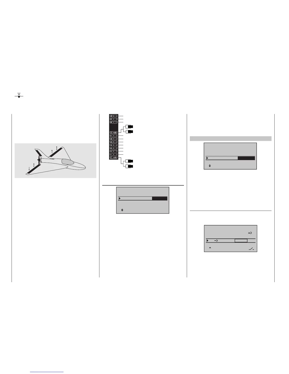
Receiver power supply
Free or aux. function
Free or aux. function
Left elevon
Right elevon
Free or aux. function
Receiver power supply
Airbrake or throttle servo
or speed controller (electric motor)
Free or aux. function
Free or left flap / elevator
Free or right flap / elevator
Free or aux. function or left flap 2 / elevator
Free or aux. function or right flap 2 / elevator
Free or rudder
According to the assignment of the receiver outputs, in
the menu …
»Model type« (page 98)
None
2AIL
In 1+100%
SEL
Delta/fl
Tail type
Motor at C1
Aile/flaps
Model type
Brake Off
… the necessary settings are made:
• “Motor an C1”
“None” or “Throttle min front/back”
• “Tail type”
“Delta/fl”
• “Aileron/camber aps”
“2AIL” (appears automatically).
To the extent necessary – and if with the respec-
tive transmitter possible – expand default “2 AIL” by
4AIL or 1, 2 or 4 camber flaps (“1 FL”, “2 FL” or “4
FL”).
• “Brake”
stays as is, only interesting for a delta wing or flying
wing of type “2/4AIL 1/2/4 FL”. In this case, refer
Delta and ying wing
to the text under “Brake offset” on page100.
These model type specifying settings primarily affect
the functions made available in the »Wing mixers«
menu. Therefore, the options are discussed separately
for two-flap and multi-flap models in the following:
Delta/ying wing of the type: “2AIL”
+100%
SEL
Delta/fl
2AIL
None
In 1
Tail type
Motor at C1
Aile/flaps
Model type
Brake Off
By retaining the standard default “2 AIL” in the “Aileron/
flaps” line, elevator and aileron control, including the
trim function, are automatically mixed by percen tage on
the software side. However, on the transmitter side, the
percentage effect of the elevator and aileron stick can
be influenced in the »Dual Rate / Expo« menu, page
126.
Settings in the menu …
»Wing mixers« (beginning on page 166)
… are, if need be, advantageous with the “AI RU”
mixers and are “played’ with a great deal of “feel” for
flying behavior with minor differentiation values.
Aile.diff
Brake settings
+10%
AI
+50%
Wing mixers
HR WK 0%0%
–––
–––
RU
normal
Due to the specific idiosyncrasies of this model type,
additional settings lead to moments which cannot be
compensated.
Of course, the general comments regarding the instal-
lation and the adjustment of the RC system to a model
at the beginning of the wing model programming on
page 278 also applies for delta and flying wing mod-
els! Similarly, the comments for test flying and fine-
tuning the settings to the programming of flight phases
also apply.
left
right
Delta and flying wing models differ significantly from a
“normal” flight model due to their unique characteris-
tic shape and geometry. The differences in the servo
arrangement, on the other hand, are more subtle. For
example, with “classic” delta/flying wing models, only
two rudders are normally provided. They are respon-
sible for both “transverse” and “height/depth”, like the
side rudder/elevator function on a V-tail unit.
With more elaborate designs, on the other hand, it
may be the case that one (or two) interior rudders
have only an elevator function and the exterior ailerons
only support the height/depth function, under certain
circumstances. Even with a 4, or indeed up to 8, flap
wing the use of camber flap functions and/or even a
crow system is nowadays entirely possible. In all these
cases, however, the following assignment of the re-
ceiver outputs should be used, see also page65.
Unneeded outputs a simply left free:

 Loading...


