52
Receiver initialization
Receiver initialization
Preliminary remarks
Receiver system
Included with the remote control sets
mc-16 HoTT
is a bi-directional 2.4GHz receiver type GR-16 for the
connection of up to 8 servos and supplied with the
remote control sets mc-20 HoTT is a bidirectional
2,4 GHz-type receivers GR-24 for the connection of up
to 12 servos.
In addition, each of the two sets includes a receiver
GR-12L for connection of up to 6 servos.
If you have to set the
mc-16 HoTT with the included
GR-16 HoTT receiveror the Set the
mc-20 HoTT
with the included GR-24 HoTT receiver is turned on
and “his” transmitter is not in range or turned off, or
possibly even the transmitter is on the “wrong” model
memory, the red LED lights of the respective receiver
for about one second and then starts flashing slowly.
This means that the receivers (still) are not connected
to a Graupner HoTT transmitter. Once communication
is established, a green LED lights up permanently and
the red goes out.
To be able to connect to the transmitter, a Graupner
HoTT receiver must be “connected” to “his” Graupner
HoTT transmitter with “his” model memory initially.
This process is known as “binding”, see pages 80 and
90. This “binding” is only required once per receiver
/ model memory combination or - after appropriate
conversion of one or more model memory, see page
79 or 89 - only each receiver / transmitter combina-
tion and was factory made in each kit receiver GR-16
HoTT or GR-24 HoTT for the model memory 1, so that
the “binding” is necessary only when additional receiv-
ers or a space change occur (and at any time can be
repeated).
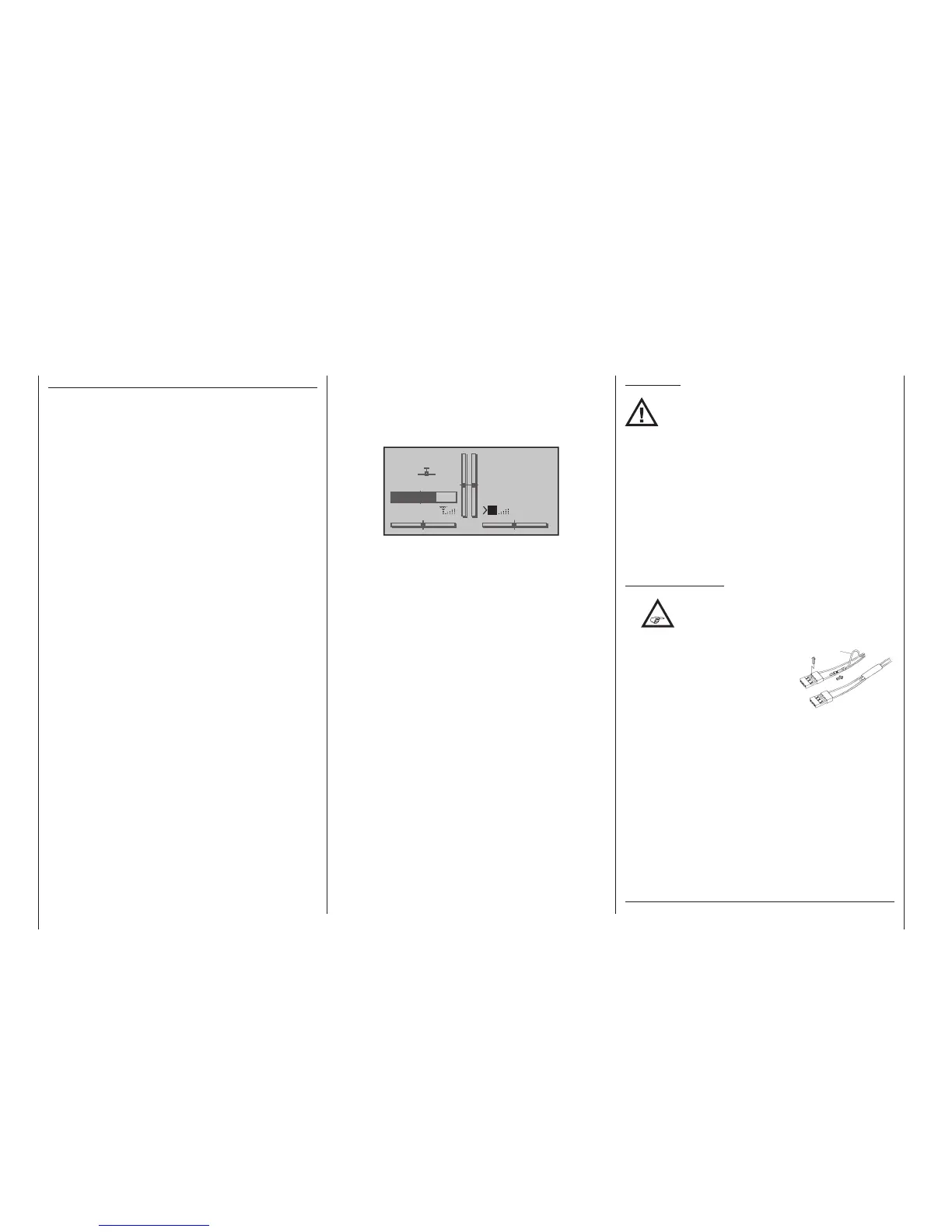
On-board voltage display
The current voltage of the receiver’s power supply will
be shown in the right side of the transmitter’s screen if
a telemetry link exists between the receiver and trans-
mitter:
GRAUBELE
#01
2:22h
Stp
Flt
«normal »
K78
0:00
0:00
5.5V
3.9V
M
HoTT
Temperature warning
Should the receiver’s temperature sink below an adjust-
able threshold (default value -10 °C) or rise above an
adjustable threshold (default value +55 °C), an acoustic
warning will be issued by the transmitter in the form of
a uniform beep of about 1 s duration. The aforemen-
tioned threshold limits are stored and adjusted in the
receiver.
Servo connections and polarity
Graupner HoTT receiver servo connections are num-
bered. The connectors used are keyed against polarity
reversal. Pay attention to the small side chamfers when
plugging in these connectors. Never use force.
The supply voltage is bussed across (i. e. common for)
all numbered connections.
The two vertical sockets at the extreme edge of the
GR-16 and GR-24 receivers are intended for the bat-
tery connection. On the GR-16 these two sockets are
marked “1+B-” and “6+B-”. On the GR-24 these two
sockets are marked “11+B-” and “12+B-”. However,
you can also connect the corresponding servos to
these two sockets in parallel with the power supply
simply by using a Y-lead, No. 3936.11.
CAUTION:
Do not reverse the polarity of this connec-
tion. Reversed polarity could destroy the
receiver and devices attached to it.
The function of every individual channel is determined
by the transmitter used, not by the receiver. It is not
only the throttle servo connection which is different for
every manufacturer and model type. For example, in
Graupner remote control systems the throttle servo is
on channel 1 for winged aircraft and on channel 6 for
helicopter models.
Follow the installation instructions on page 54 for
the receiver, the receiver antenna and for mounting the
servo.
Concluding notices:
•
The signicantly greater servo resolution
characteristic of the HoTT system produc-
es a noticeably rmer response behaviour
in comparison to previous
technology. Please take the
time to familiarize yourself
with this sensitive behaviour.
• If you have a speed control-
ler with integrated BEC* ar-
ranged in parallel with the re-
ceiver battery, its positive pole (red cable) may to
be removed from the 3-pole connector. Be sure
to look for notices about this in the instructions for
the speed controller used.
With a small screwdriver, carefully lift up the con-
nector’s centre latch (1) just a bit then pull out the
red lead (2) and tape it up with insulation tape to
prevent possible short circuits (3).
* Battery Elimination Circuit
red
1
2
3

 Loading...


