260
Program description - Ring limiter
Ring limiter
Control of Voith Schneider propellers in model ships
This option is available on the mc-20
HoTT transmitter only.
Scroll with the selection keys on the left or
right four-way button to the menu option
»Ring limiter« in the multi-function menu:
Trim memory
Telemetry
Channel sequence
Multichannel
Ring limiter
MP3 player
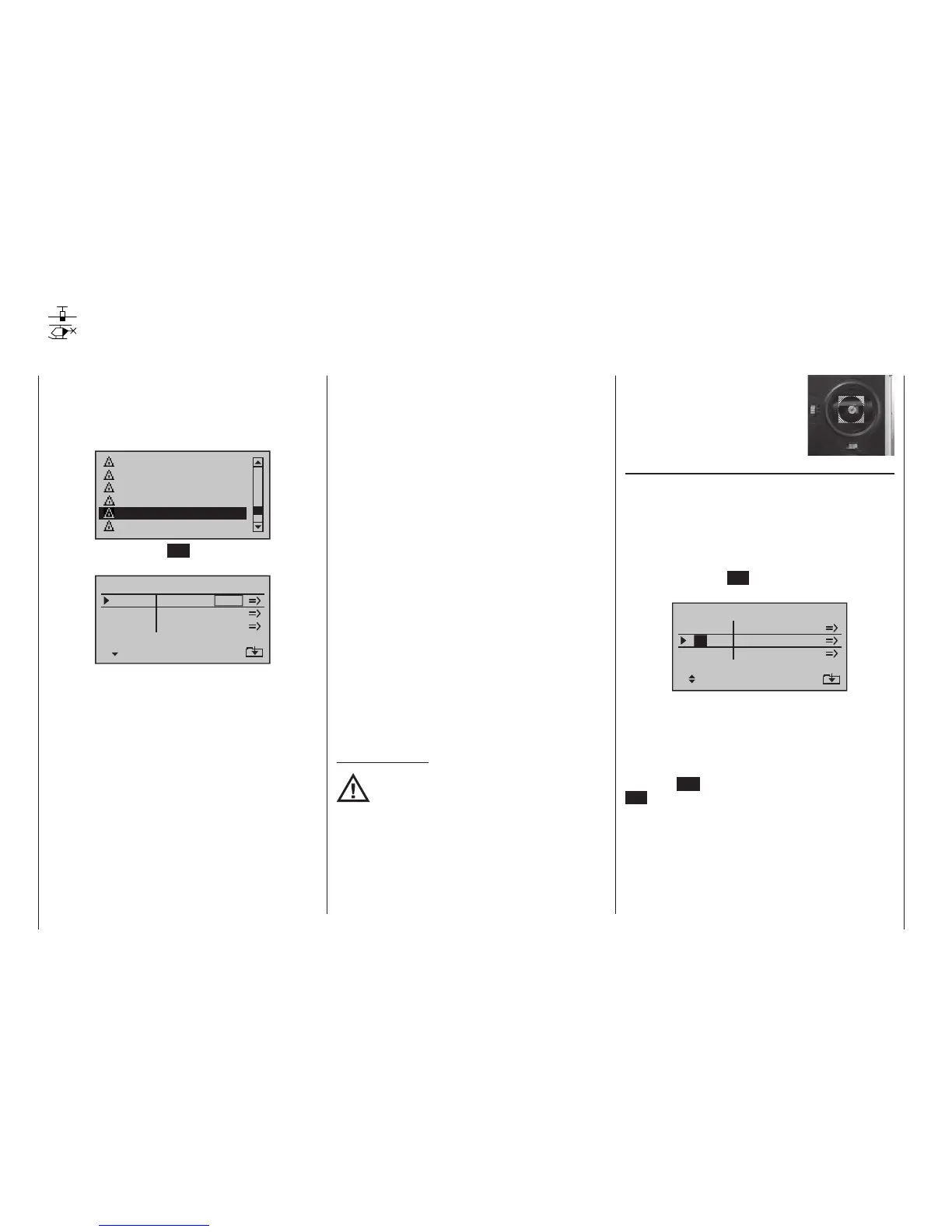
Tap briefly on the centre SET key of the right four-way
button to open this menu option:
4
4
4
Ring limiter
Input
SET
3
9
11
OFF
OFF
OFF
Output
X
3
3
3
Y Y
4
10
12
X
This »Ring limiter« menu point is available as standard
on the mc-20 HoTT transmitter only, and is primarily
intended for controlling a maximum of three Voith-Sch-
neider power systems as employed in model boats.
These are positioned beneath the ship where they are
exposed to a free flow of water in all directions. The
control of these drives and turning their vertically orient-
ed propeller blades is done with two servos per Voith
Schneider propulsion unit whereby, for mechanical
reasons, the propellers of this type offered by Graup-
ner under No.. 2358 and 2358.BL have a maximum
control travel limitation of 4 mm each.
As long as the sticks for forward/reverse and left/right
are operated individually (see section “Column Input”)
this is no problem because travel for the two servos
can be appropriately adjusted, both mechanically as
well as in the »Servo adjustment« menu. However,
this becomes problematic when, for example, one stick
is 100 % forward and, at the same time, the other stick
is pushed completely to the right to arithmetically pro-
duce a 141 % sum for the two servo travel vectors. The
mechanical controls of the Voith Schneider propellers
will collide with their limits; in best case only drawing an
unnecessary amount of electric current, in worst case
causing damage or even bursting the linkage..
This problem can be circumvented by using “ring limit-
ers”, which are featured only on the
mc-20 HoTT
transmitter. There are a maximum of three “ring limit-
ers” available in the “SET” column of this option’s first
display page (see figure at left) that can be switched
“ON” or “OFF” individually. In the first line on the setting
page for a given “ring limiter”, its maximum travel can
then be set for a range of between 25 and 125 %. The
second line provides a setting for the size of limitation
of overall deflection between:
0 % circular limit ()
100 % no limit ()
(limitation is strictly a matter of the given stick’s
mechanical stop)
Important notice:
When this function is used, leave the
respective setting values in the »Dual Rate
/ Expo« and »Servo adjustment» menus at
0 and 100 % or reset them back to their default
values.
The adjacent sketch illustrates the
effect for a 0 % setting. The cross-
hatched area of travel is curtailed
and appears as a “dead zone”.
Column, “Input”
With the standard preset control mode 1, all three ring
limiters are pre-assigned to inputs 3 (forward/reverse)
and 4 (left/right) which are actuated by the left stick.
However, this pre-assignment can be replaced anytime
by any other transmitter control combination. Use the
selection keys on the left or right four-way button to
move the marker frame to the desired value field then
briefly tap the centre SET key of the right four-way
button:
4
4
Ring limiter
Input
SET
3
9
11
OFF
OFF
OFF
Output
X
3
3
3
Y Y
4
10
12
X
4
Select the desired control channel (1 … 12 max.) for
the value field now displayed in inverse video by using
the or selection keys. However, do not forget
that if a control channel in the range of 5 … 12 max. is
selected, it must also be assigned to a control in the
»Control adjust« menu, see page 112. Briefly tap
the centre ESC of the left four-way button or the centre
SET key of the right four-way button to conclude your
entry.
In principle, the other inputs are to be handled in the
same manner.
A tap on the or keys of the right four-way
button at the same time (CLEAR) will reset the active
value field back to its given default value.
mc
16 20

 Loading...


