130
Program description - Dual Rate / Expo | Helicopter models
Dual Rate / Expo
Configurable control characteristics for roll, pitch-axis and tail rotor
This option is available on both transmit-
ter types.
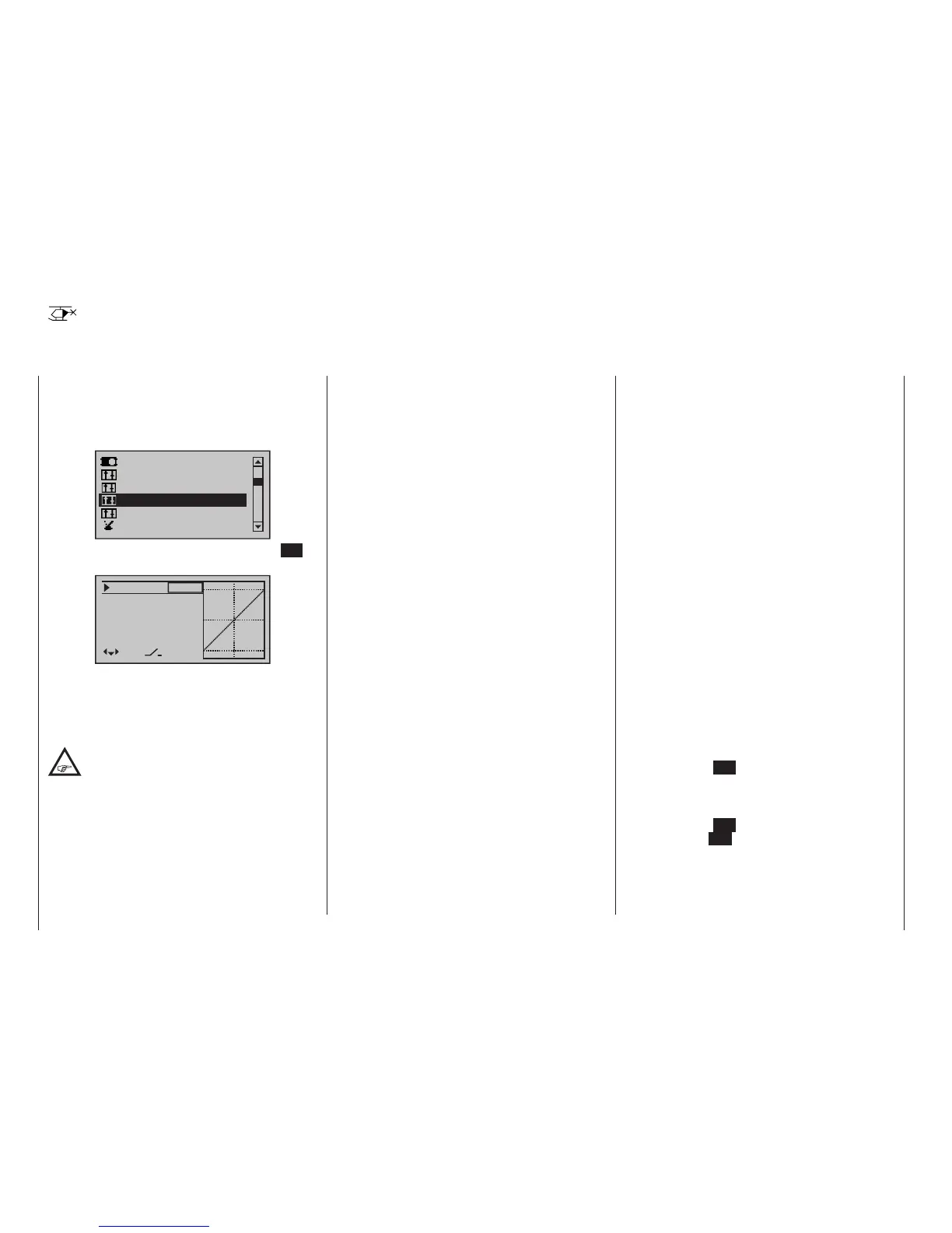
Use the selection keys of the left or right
four-way button to scroll to the »Dual Rate
/ Expo« menu option in the Multi-function menu:
Servo adjustment
Stick mode.
Channel 1 curve
Switch display
Control adjust.
Dual Rate / Expo
Open this menu option with a tap on the centre SET
key of the right four-way button:
100%
100%
100%
Roll
Nick
Tail
DUAL
–––
–––
–––
SEL
The Dual Rate / Expo function permits switching or
controlling of control travels and characteristics for the
control functions roll, pitch-axis, tail rotor, i. e. control
functions 2 … 4; it is switch-driven and flight-phase
independent.
It is possible to set up an individual curve for
control function 1 (throttle / collective pitch)
using a maximum of six separately program-
mable points. This is carried out in the »Channel 1
curve« menu, which is available on the mc-16 HoTT
and the mc-20 HoTT transmitter; see the section
starting on page 137. It can also be set up for throttle
and collective pitch separately in the »Helicopter
mixer” menu, which is available on both transmitters;
see the sections starting on pages 184 and 324.
Similar to control travel settings in the »Control ad-
just« menu, Dual Rate operates directly on the re-
spective control function, independent of whether it
is an individual servo or multiple servos connected via
complex mixer and coupling functions.
The control travel for each switch position can be set to
between 0 and 125 % of normal full travel.
Expo, on the other hand, enables finer-grained con-
trol of the model for values larger than 0 % around the
centre position of the primary control function (roll,
pitch-axis, tail rotor), without forfeiting full movement at
the end-points of stick travel. For values less than 0 %,
the reverse is true: control increases around the neutral
position and diminishes towards the end-points. The
degree of “progression” can therefore be set within a
total range of -100 % to +100 %, where 0 % equates to
the normal, linear control characteristics.
Rotary-output servos, now generally commonplace,
offer another application. This is because the actual
control surface movement is not linear: as the rotational
angle of the output disc or lever increases, the control
surface rate of travel over the control linkage continually
decreases – depending on the position of the linkage
point on the output disc. This effect can be counter-
acted with Expo values greater than 0 % such that
rotational angle travel increases over-proportionally with
increasing stick throw.
The Expo setting also affects the relevant control func-
tion directly, whether this controls a single servo or
multiple servos – via any number of mixer and coup ling
functions.
For both Dual Rate and Expo functions, switch as-
signment can be set up in any way desired, which
therefore permits the triggering of multiple functions
using one and the same switch. This, in turn, offers the
opportunity to link the triggering of Dual Rate and Expo
functions to a single switch: this offers many advan-
tages – particularly for very high-speed models.
The graphic screen displays the curve characteristics
directly. Once you select a menu line, the dotted verti-
cal line follows the movement of the respective stick,
so you can clearly see the dependency of the curve
value on the transmitter control.
Flight phase-dependent Dual Rate and Expo set-
tings
If flight phases are set up in the »Phase settings«,
page 152, and »Phase assignment« menus, page
154, and each assigned a name,e. g. “Normal”, the
name in question will be displayed at the bottom left of
the display. In this scenario, you can operate the corre-
sponding switch to switch between flight phases.
Basic procedure
1. Switch to the desired flight phase then use the
selection keys of the left or right four-way button to
select the desired line: “Roll”, “Pitch ax” or “Tailrot”.
2. Use the selection keys of the left or right four-
way button to select the right column or the as-yet
invisible column for Expo values, see page 33.
3. Tap the centre SET key of the right four-way button.
The corresponding input field is shown highlighted.
4. Use the selection keys of the right four-way button
to set the desired value.
5. Tap the centre SET key of the right four-way button
or the central ESC key of the left four-way button to
complete the entry.
6. A simultaneous tap on the or keys of the
right four-way button (CLEAR) will any setting made
back to its respective default value.
mc
16 20

 Loading...


