116
Program description - Control adjust | Helicopter models
Control adjust
Basic procedure for transmitter control and switch assignment
This option is available on both transmit-
ter types.
Use the selection keys on the left or right
four-way button to scroll to the »Control
adjust« option in the multi-function menu:
Servo adjustment
Dual Rate / Expo
Stick mode
Channel 1 curve
Switch display
Control adjust
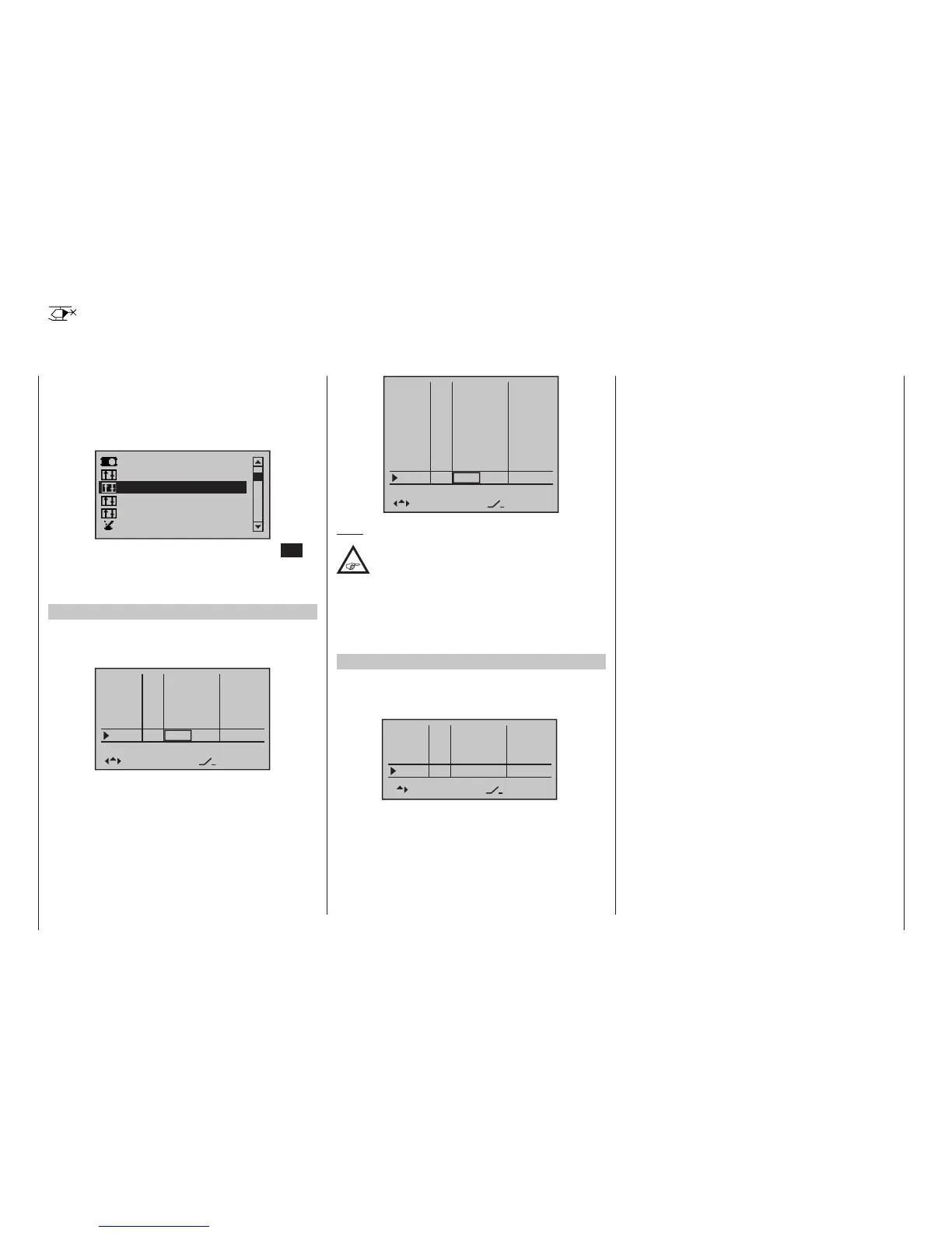
Open this menu option with a tap on the centre SET
key of the four-way button pad. On the standard eight-
channel mc-16 HoTT transmitter this looks as fol-
lows:
Firmware version V1102 and lower
By default, the input preset to the right side of the
transmitter mounted proportional rotary slider SD2
“Lim.”:
In5
offset
Thro
Gyro
Lim.
–––
–––
–––
Lv2
0%
0%
0%
0%
GL
GL
GL
GL
typ
fr
fr
fr
–––
SEL
–––
0%
GL
fr
In8
On the twelve-channel mc-20 HoTT transmitter, this
looks as follows:
In5
offset
0%
0%
0%
Thro
Gyro
In8
–––
–––
–––
In9
In10
In11
Lim.
–––
–––
–––
Lv2
0%
0%
0%
0%
0%
–––
GL
GL
GL
GL
GL
GL
GL
GL
typ
fr
fr
fr
fr
fr
fr
fr
–––
SEL
Note:
To save space the remaining screen-shots in
this section are based on the display of the
standard eight-channel mc-16 HoTT
transmitter. The pictures also apply in similar manner
to the twelve-channel mc-20 HoTT transmitter,
since the only difference between the transmitter
displays is the lines “In8” to “In11” located between
“Gyro” and “Lim.”.
Firmware version V1103 and higher
From the firmware version of the “Lim” input after initial-
izing a new model memory with the model type “Heli-
copter” is enabled by default “free”:
Gas
offset
Gyro
In8
–––
–––
–––
0%
0%
0%
GL
GL
GL
typ
fr
fr
fr
SEL
–––
0%
GL
fr
Lim
Although the basic hardware features of the mc-16
HoTT and mc-20 HoTT transmitters are the same,
i. e. two dual-axis sticks for control functions 1 to 4 and
the associated trim levers, the standard supplementary
controls fitted to the two transmitters are different.
•
mc-16 HoTT
• two 3-way switches (SW 5/6 & 11/12)
• two proportional sliders on the middle console,
designated Sl 1 & 2 in the menu
• two side-mounted “rotary sliders”, designated
Lv1 and 2 in the menu
•
mc-20 HoTT
• three 3-way switches (SW 2/3, 5/6 & 11/12)
• five 2-way switches (SW 4, 7, 9, 13 & 15)
• two self-restoring 2-way switches (SW 8 & 14)
• two unlockable 2-way switches (SW 1 & 10)
• two push-buttons on the back-side of the trans-
mitter (SW 16 & 17 bzw. 18 & 19)
• two switch-keys (Gb5 & Gb6)
• two proportional sliders on the middle console,
designated Sl 1 & 2 in the menu
• two side-mounted “rotary sliders”, designated
Lv1 and 2 in the menu
In contrast to the two sticks which, even for a newly
initialized “Helicopter” model type will automatically use
the servos attached to receiver outputs 1 …4 and 6,
the aforementioned “other” operating elements – except
for the standard assignment of servo 6 to the right-
side proportional slider, designated in this menu as Lv2
(throttle limiter) – are initially inactive.
One of the effects of this is that (as already mentioned
on page 70) with a factory-fresh system – as with a
newly initialized model memory for a “Helicopter” mod-
el type following its “binding” to the intended receiv-
er – only those servos connected to receiver outputs
1 … 4 and – depending on the position of the throttle
limiter – servo 6 can be moved by the two sticks. Any
servos connected to plug-in locations 5, 7 and 8 or 5,
7 through 12, on the other hand, will simply remain at
their centre positions.
mc
16 20

 Loading...


