117
Program description - Control adjust | Helicopter models
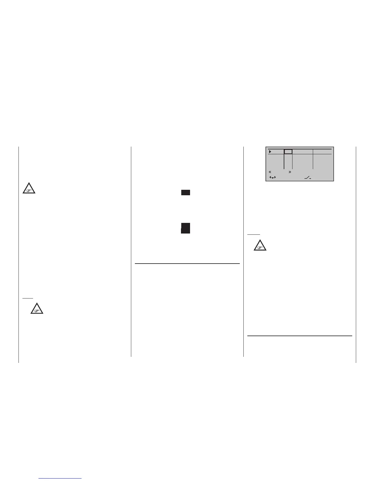
In5
offset
0%
0%
0%
–––
0%
Thro
Gyro
In8
–––
–––
–––
GL
GL
GL
GL
typ
normal
fr
fr
fr
fr
SEL
• “GL(obal)“
The settings for the input in question affect all flight
phases programmed (if any) and thus act “globally”
on the model memory in question.
“PH(ase)”
The settings for this input take effect per flight
phase and must therefore be configured separately
for each flight phase.
Notes:
•
The current positions of the INC/DEC but-
tons CTL 5 & 6, which are generally as-
signed to inputs 5 … 8 or 5 … 12, are
stored in accordance with your chosen entry in the
“Type” line, i. e. the settings are not lost when you
switch ight phases or change models.
The particular advantage of these two transmit-
ter controls – especially if you select the “PH” set-
ting – lies in the fact that you can use one and the
same INC/DEC button as trim controls in all the
programmed ight phases,
but – in contrast to a position-related proportion-
al control – the trim values are retained even if you
change models.
• See page 146 for more information about ight
phases.
Column 3,
“Transmitter control/switch assignment”
Using the selection keys of the left or right four-
way button to select an input: In5, Thro, Gyro or Lim.
respectively In5, Thro, Gyro, In8 … 11 or Lim.
While this may appear a bit awkward at first glance …
this is the only way to ensure a completely free selec-
tion from among “additional” operating elements while,
at the same time, not requiring the “deactivation” of
unused operating elements.
This is because:
The only way to ensure an unused operat-
ing element can have no effect on the
model, even if operated by accident, is to
make it inactive, i. e. not assigned to any function.
All of the aforementioned operating elements can be
freely assigned in this »Control adjust« menu to any
function input, see page 58, just to accommodate
personal requirements. Equally, this also means that
each of these operating elements can also be assigned
to multiple functions at the same time, as needed. For
example: the exact same toggle switch assigned to
an input in this menu can, at the same time, also have
an assignment in the »Timers (general)« menu as an
“On/Off” switch, etc.
Furthermore, all inputs can be selectively set to global
or ight-phase specic operation if they have been de-
fined for flight-phases in the »Phase settings« menu,
page 152, and »Phase assignment« menu, page
154. The names assigned to given flight phases then
appear in the second-from-the-bottom display line,
e. g. «Normal».
Note:
•
As a rule, input 6 must kept “free” for a
helicopter model. On this, see “Throttle”
on the next double page.
• However, unlike the travel adjustment affects all
of the control travel setting outgoing mixer and
coupling inputs, ie all servos which are operated
by the control.
Basic procedure
1. Use the selection keys of the left or right four-
way button to select the desired input: In5, Thro,
Gyro or Lim. respectively In5, Thro, Gyro, In8 … 11
or Lim.
2. If necessary, use the selection keys of the left
or right four-way button to select the desired co-
lumn.
3. Briefly tap the centre SET key of the right four-way
button. The corresponding input field is shown high-
lighted.
4. Operate the chosen operating element or set the
desired value with the selection keys of the right
four-way button.
5. Briefly tap the centre SET key of the right four-way
button or the central ESC key of the left four-way
button to complete data entry.
6. A simultaneous tap on the or keys of the
right four-way button (CLEAR) will any setting made
back to its respective default value.
Column 2, “typ”
Similar to the previously described »Stick mode«
menu, this column can be used to define whether fur-
ther settings for the given input are to have a “GL(obal)”
or a “PH(ase-specific)” effect. Do this by using the se-
lection keys of the left or right four-way button to select
the desired input In5, Thro, Gyro or Lim. respectively
In5, Thro, Gyro, In8 through In11 or Lim. in the column
labelled “typ”, for example:

 Loading...


