40
Transmitter description - Telemetry data display
The
mc-16 HoTT transmitter features a single screen
below the aerial socket which is used both for operat-
ing the transmitter and also to display telemetry data in
graphic form. You can switch between the two operat-
ing modes by pressing one of the Select buttons
or of the left-hand four-way button in the base
display.
The
mc-20 HoTT transmitter has two independent
displays; a display for operating the transmitter and a
display just below the antenna socket for the graphic
display of telemetry data. This display is activated auto-
matically as soon as the transmitter receives telemetry
data from the receiver via the return channel.
GRAUBELE
#01
0:00h
Stp
Flt
«normal »
K78
0:00
0:00
0.0V
4.1V
Mx
HoTT
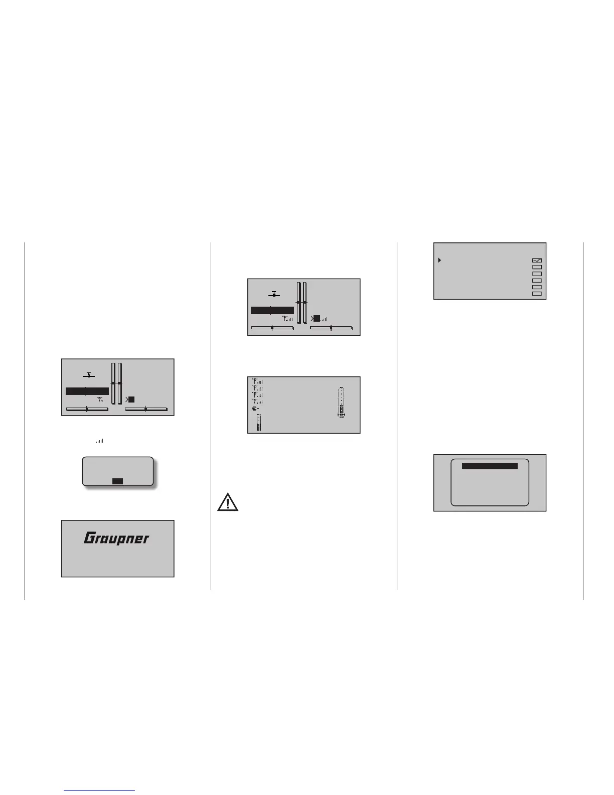
If however, at the lower edge of the base display, only
“X” – as shown in the fi gure above – is displayed at two
locations instead of “ ”, then the telemetry display will
show the warning …
CAN‘T
RECEIVE
DATA
OK
…, on the front screen of the mc-20 HoTT, dis-
placed shortly afterwards by the Graupner logo and
the transmitter name …
mc20
…, and this means that there is no receiver within
range capable of exploiting the telemetry link. Switch
on the model’s receiver system or bind a receiver to the
active model memory as described in detail on page
80 or 90.
GRAUBELE
#01
0:01h
Stp
Flt
«normal »
K78
0:00
0:00
4.8V
4.1V
M
HoTT
If a telemetry link is present, the front screen of the
mc-20 HoTT shows the “Receiver” display by de-
fault. The same occurs on the mc-16 HoTT transmit-
ter after you select the Telemetry display mode …
RX–S QUA: 100%
RX–S STR: 100%
TX–dBm: –33dBm
RX–dBm: –33dBm
RX–VOLT:4.8V TMP
L–PACK: 10ms
CH OUTPUT TYPE:ONCE
R–LOW V:4.6V +22°C
… which is described in more detail in a section by the
same name on the next page.
Sensor Select
Up to four sensors can be connected, in any combina-
tion, to a telemetry-capable receiver.
The data output of these sensors in the graph-
ic displays described below must be accepted
if they have been properly connected before
turning on the receiver on this and afterwards also
recognized automatically via the return channel from
the transmitter.
For transmitters with fi rmware version number lower
than V1.010 (
mc-16) or V1.030 (mc-20), in con-
trast, as described on page 250 under the sub-menu
“SENSOR (SELECT)” of the “Telemetry” - described
menus, ...
SENSOR SELECT
RECEIVER
GENERAL MODULE
VARIO MODULE
ELECTRIC AIR.MOD
GPS
ESC
… in order to activate their display. This data from the
selected sensors is then appropriately prepared for
illustration by the graphic indicators as described be-
low. You must also ensure that the receiver selected in
the “Telemetry receiver” line of the »Telemetry« menu
(Bind 1 or 2) is the one to which the sensors are con-
nected; see pages 80 and 90. If you select the
“wrong” receiver, the “Receiver” display will only show
the data from that unit.
Furthermore, only sensors activated in the »SETTING
& DATAVIEW« sub-menu of the »Telemetry« menu,
beginning page 238, according to the instructions
included with the given sensor will be responsive.
To switch between the screens for activated sensors in
the »SENSOR SELECT« sub-menu of the »Tele metry«
menu, tap briefl y on one of the selection keys of
the left or right four-way button …
RX–S QUA: 100%
RX–S ST : 100%
TX–dBm: 33dBm
RX–dBm: 33dBm
RX–SPG.:4.8 TMP
V–PACK: 10ms
CH OUTPUT TYPE:ONCE
GENERAL
ELECT. AIR
VARIO
GPS
RECEIVER
AIR ESC
… and, after the selected screen has been displayed,
use one of the two keys to select the line of the
desired sensor.
Telemetry data display

 Loading...


