24
Transmitter description - Face-side connections
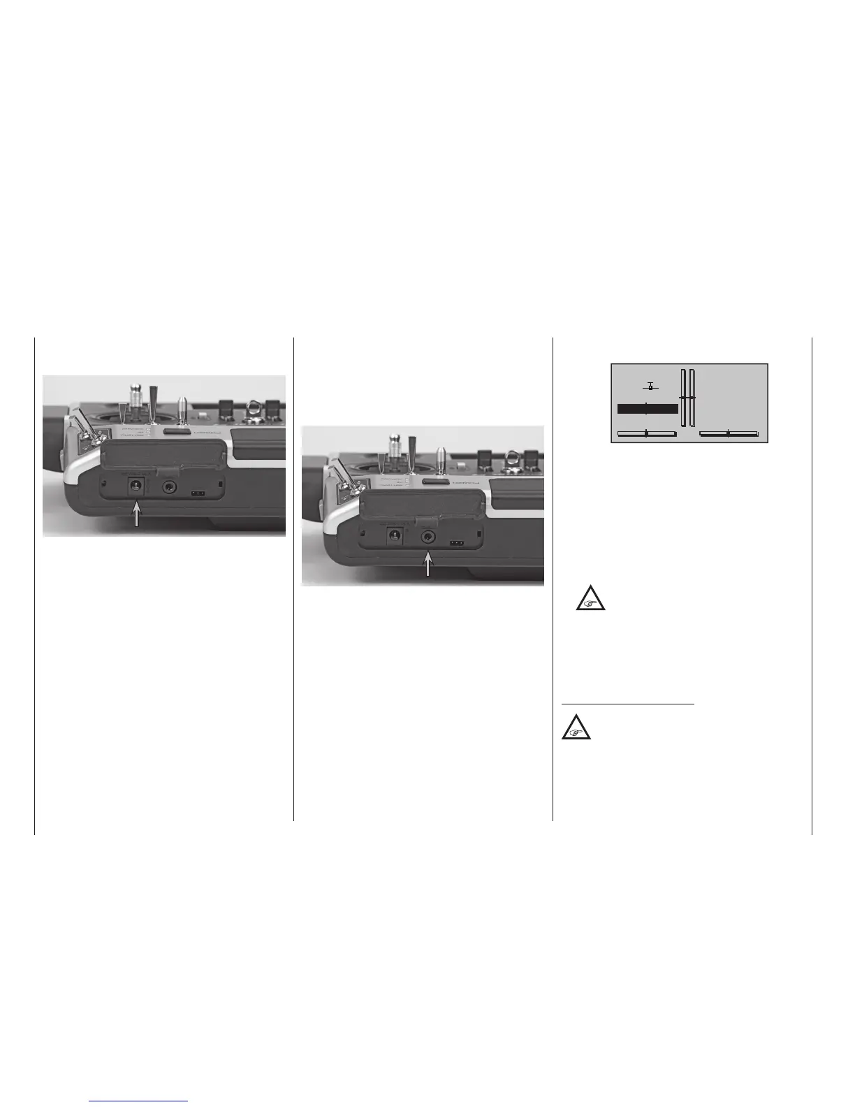
clock. At this time, the display of telemetry data and
symbols will be suppressed.
PUPIL
#11
0:01h
Stp
Flt
«normal »
DSC
0:00
0:00
4.1V
0.0V
HoTT
The transmitter’s upper display will show the mes-
sage “CANNOT RECEIVE DATA” during this time.
Thus the transmitter is ready for operation.
In contrast, the transmitter in teacher mode is to be
switched on prior to plugging in the respective ca-
ble.
3. Connect the other end of the cable to the desired
unit in compliance with the given operating instruc-
tions for that unit.
Important:
Pay attention that all plugs are inserted
securely into their respective sockets
and use only the prescribed 2-pole TRS
connector plugs on the DSC-side.
4. In the line “DSC Output“ in the »Basic settings,
model«, page 85 or 95, – depending on the
number of functions transferred – one of the follow-
ing modes can be set: PPM10, PPM16, PPM18 or
PPM24. Default setting: PPM10.
Notice about ight simulators:
Because of the myriad of ight simulators
available on the market, it may be necessary
to have the contact layout of the audio plug or
DSC module appropriately modied by Graupner
Service.
DSC jack
The acronym “DSC” is a carryover which stands for
the original “Direct Servo Control” function. However, in
HoTT systems the “direct servo control” function is no
longer available via a diagnose cable due to technical
reasons.
Once the left-hand side flap has been moved away, the
DSC socket is accessible:
The two-pole DSC socket fitted as standard to mc-
16 HoTT and mc-20 HoTT transmitters serves both
as Trainer socket (Teacher and Pupil) and also as inter-
face for flight simulators and external RF modules.
To ensure a proper DSC connection, please ob-
serve:
1. Make any necessary menu changes.
Refer to the section beginning on page 218 to
adapt the transmitter to a teacher/pupil system.
2. When operating a flight simulator or when operat-
ing the transmitter as a pupil transmitter, ALWAYS
switch OFF the transmitter as only in this position
does the transmitter‘s RF module remain inactive
after the DSC cable is inserted. This also reduces
the transmitter‘s power consumption somewhat.
Only the red LED should remain constantly illuminat-
ed and the transmitter’s basic display should show
the character string “DSC” below the operating time
Face-side connections
Charger socket
(The illustration shows the mc-20 HoTT transmitter.)
The left-hand side flap provides access to the charge
socket of the
mc-16 HoTT and mc-20 HoTT
transmitter:
The transmitter’s rechargeable LiIo battery can be
charged by way of the charger socket located behind
a cover on the left, front side of the transmitter – as
viewed from the front – with the included plug-in charg-
er (No. 32032.4).
Maximum permissible charging current with Graupner
automatic chargers: 1,5 A.
Never use plug-in chargers from other manufacturers
or chargers intended for other battery types. Charger
output voltage which is too high or possibly even dif-
ferent plug polarity, see further below, can cause im-
mense damage.
More information about charging the transmitter’s bat-
tery can be found on page 18. Observe the safety
notices beginning on page 8 when handling lithium
batteries.

 Loading...


