304
Programming examples - Using ight phases
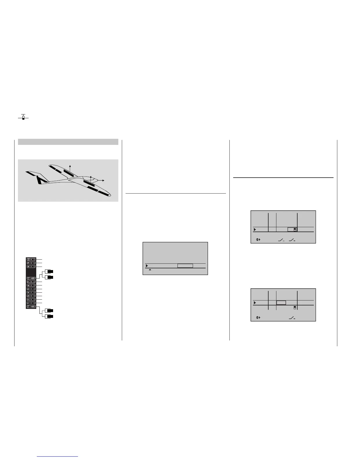
Example 2
Glider with four ap wings, two large aps and
tow coupling
AI
FL
FL
AI
EL
RU
The following example is based on the assumption that
you have already mechanically pre-adjusted the model
and you have already ensured the correct deflection of
all rudders or checked this again in the scope of this
programming and made adjustments, if applicable,
through servo switching at the receiver and/or through
the »Servo adjustment« menu.
This programming example is based on an assignment
of the receiver connections in accordance with the fol-
lowing diagram:
Receiver power supply
Free or aux. function
Free or aux. function
Aileron or left aileron
Elevator or left rudder / elevator
2nd airbrake servo or 2nd elevator or aux. function
Receiver power supply
1st airbrake servo
Right aileron
Flap or left flap
Right flap
Aero-tow release or free or aux. function
Free or aux. function
Rudder or right rudder / elevator
Begin with the new programming of the model in a free
model memory location.
Essentially, the »Base setup model« menu, beginning
on page 78, is used to bind the receiver to the trans-
mitter. Enter a model name and select or review the
selection of appropriate stick mode. Later on this menu
will also be used to activate the range test before the
start of flight operations.
In the menu …
»Model type« (page 98)
…leave “Motor at C1” at “none”, and the tail type at
“normal”. However, set “2 AIL 2 FL” in the “Aileron/
flaps” line.
In the “Brake offset” line program or leave “In1”, be-
cause the two brake or spoiler servos connected to
1 + 8 will eventually be controlled by the C1 stick, in
addition to the butterfly (crow) braking system which is
set up in the “Brake settings” sub-menu of the »Wing
mixer« menu:
Tail type
Motor at C1
Normal
Aile/flaps
2AIL2FL
Model type
Brake Off In 1–90%
SEL
None
STO
The setting in the “Brake Offset” value field defines the
neutral position of all mixers specified by the “Brake
settings” sub-menu of the »Wing mixers« menu. Place
this neutral point at approx. +90 %, insofar as the brake
system should be retracted in the front position of the
C1 stick.
The remaining path between +90 % and the full throw
of the sticks, +100 %, is then assigned as idle travel.
This assures that the rudders or flaps addressed by the
mixers of “Brake settings” remain in their “normal” posi-
tions even for slight deviations from the limit position of
the C1 control. At the same time, the effective control
path is automatically spread to 100 %.
In the menu …
»Control adjust« (page 112)
… assign a switch, for example In 9, to operate the
aero-tow coupling. In order for this switch to work inde-
pendently of the flight phase, leave the standard default
“GL” in the “type” column of this input. With “– Travel
+” you can adjust the control travel for the switching of
the switch:
In6
offset
0%
0%
0%
–––
0%
In7
In8
In9
–––
–––
GL
GL
GL
GL
typ
normal
fr
fr
fr
8
–––
With a simultaneous tap on the keys of the left
four-way button, the setting can be checked in the
»Servo display«.
Since the C1 control should actuate Servo 8 simulta-
neously with Servo 1, establish this link by way of the
»Control adjust« menu.
For this reason, also switch to the line before and as-
sign “Control 1” to Input 8.
In6
offset
0%
0%
0%
–––
0%
In7
In8
In9
–––
–––
GL
GL
GL
GL
typ
normal
fr
fr
Cn1
8
–––
SEL
Using ight phases

 Loading...


