141
Program description - Control switches
Control switches
Programming the control switches
This option is available on both transmit-
ter types.
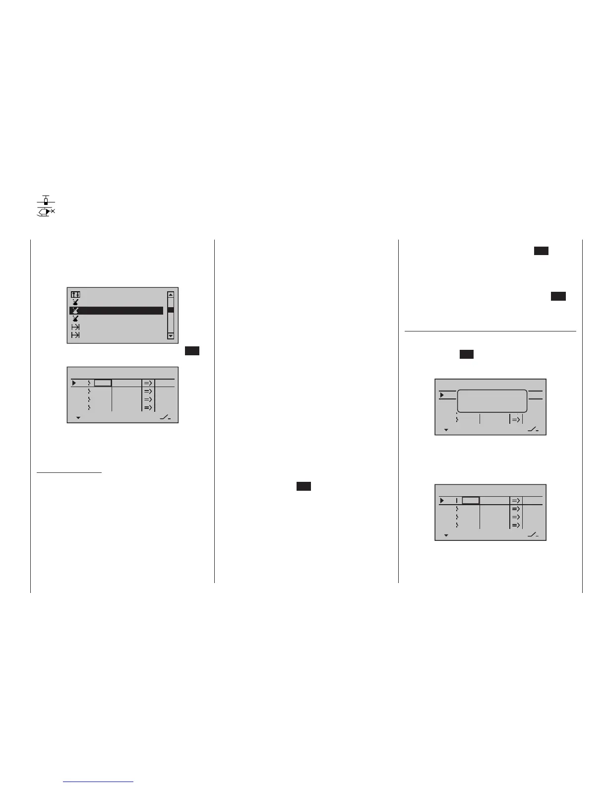
Use the selection keys of the left or right
four-way button to scroll to the »Control
switch« menu option in the Multi-function menu:
Switch display
Channel 1 curve
Phase settings
Phase assignment
Logical switch
Control switch
Open this menu option with a tap on the centre SET
key of the right four-way button:
SEL
0%
0%
0%
C1
C2
C3
–––
C4
Control switch
Gb1
Gb1
0%
STO
–––
–––
–––
SEL
With many functions, it makes sense not to trigger their
actuation by using one of the normal switches, but to
trigger them automatically by the specific, freely pro-
grammable position of a transmitter control or stick.
Typical applications:
• On/Off switching of an on-board glow plug in con-
junction with the carburettor setting and/or motor
speed. (The glow plug heater switch for this will be
controlled by a transmitter-side mixer.)
• Switching a stopwatch on or off to measure the
simple running time of electric motors
• Automated switch-off of a combi “aileron rud-
der” mixer when extending the airbrakes, e. g. so
as to match the bank attitude of the model to the
ground slope when landing on a ridge, without the
direction of ight also being affected by the rudder
(if the mixer were active).
• Lowering landing aps, adjusting elevator trim
and/or executing specic Dual Rate, Exponential
and Differential switchings when coming in to land,
as soon as the throttle stick is moved beyond the
switching point. If required, a control switch can be
overridden using a separately assigned switch in
the 5th column.
The programs of the transmitters
mc-16 HoTT and
mc-20 HoTT are equipped with a total of four so-
called control switches (“C1” to “C4”).
Accordingly, anywhere where switches can be as-
signed you have the option not only of using the
maximal 19 possible transmitter switches, but also of
choosing and assigning one of the “C1” … “C4” con-
trol switches from the list of expanded switches – as
described in the section “Physical control, switch and
control switch assignments” on page 60.
Furthermore, combining a control switch with an ad-
ditional switch (as described later) also permits more
complex switching permutations.
Basic procedure:
1. If no transmitter control is assigned, the corre-
sponding input field of the column labelled SEL
(second column from the left) will be empty.
2. Use the selection keys of the left or right four-way
button to select the line for the desired control
switch (1 to 4).
3. Briefly tap the centre SET key of the right four-way
button .
4. Move your selected transmitter control.
The associated transmitter control number appears
in the input field of the column above the left SEL.
5. Use the selection keys on the left or right four-way
button to move to the right into the column labelled
STO.
6. Move the transmitter control to the desired switch-
ing point then briefly tap on the centre SET key
of the right four-way button to save the switching
point.
7. Complete the remaining settings such as switching
direction, etc.
8. Exit from the menu with a tap on the centre ESC
key of the left four-way button .
Assigning a transmitter control to a control
switch
Using the selection keys on the left or right four-way
button, select your chosen line (1 to 4). Following a final
tap on the centre SET key of the right four-way button
to activate the control assignment, the message shown
below will appear in the display:
SEL
0%
0%
0%
C1
C2
C3
–––
C4
Control switch
Gb1
Gb1
0%
STO
–––
–––
–––
SEL
Move desired
control adj.
For example, the right-side proportional slider is now to
be assigned to control switch “C1”, the default throttle
limiter for a helicopter model memory. So just move this
control in any direction. As soon as this is detected, the
control name appears on the display:
SEL
0%
0%
0%
C1
C2
C3
–––
C4
Control switch
Lv2
Gb1
0%
STO
–––
–––
–––
SEL
mc
16 20

 Loading...


