248
Program description - Telemetry
Therefore, make sure to connect the most impor-
tant control functions to the main receiver pro-
grammed as SUMI, so that, in the event of a failure,
the model remains controllable when the SUMO
satellite receiver no longer receives a signal.
Telemetry data, such as the voltage of the on-board
electricity supply, on the other hand, is only sent to
the transmitter by the satellite receiver configured as
SUMO. For this reason telemetry sensors must be
connected to the satellite receiver (SUMO), and this
receiver must also be defined as such in the “TEL.
RCV.” line of the »Telemetry« menu (Bind 1 … 2);
see “Important notes” on page 244. Each receiver
should be connected with its own supply line from
the common voltage supply. With receivers with a
high current load, it may even be beneficial to con-
nect them with two supply lines to the same current
supply. .
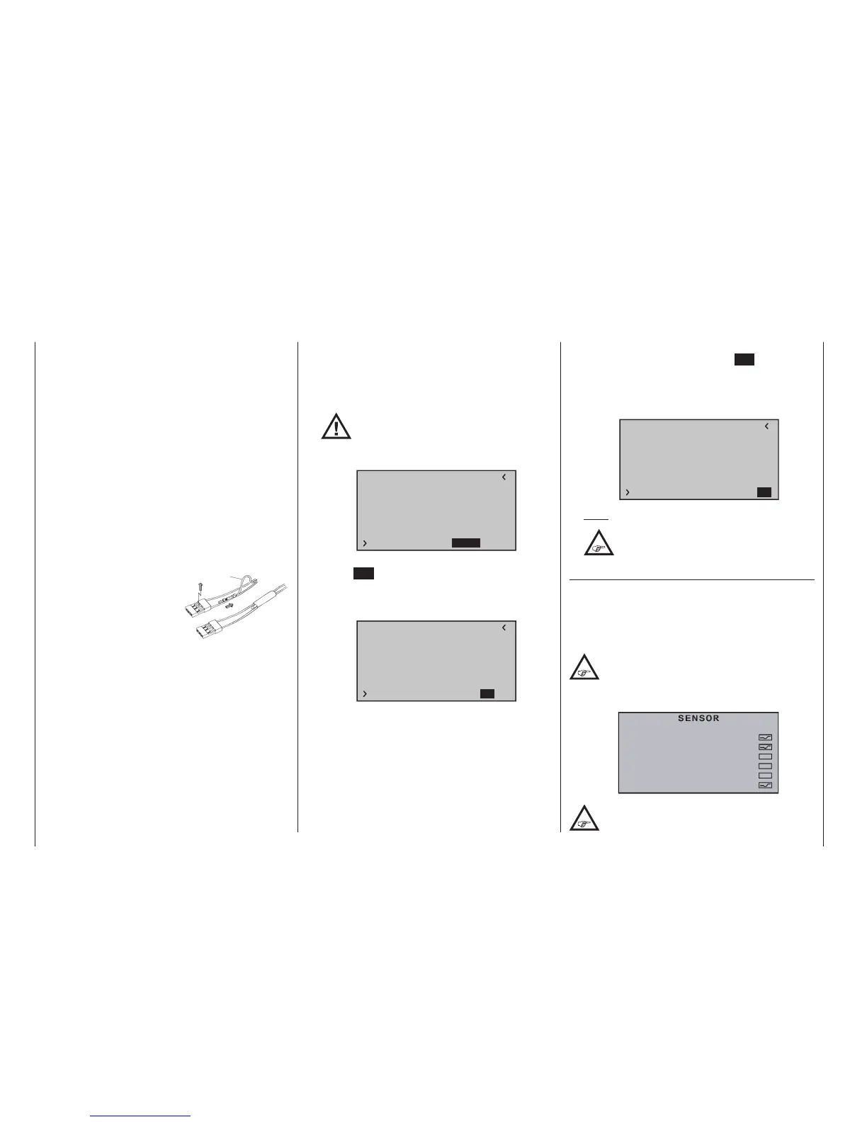
On the other hand, if each
of the two receivers should
be supplied from its own
voltage source, the cen-
tre cable must be removed
from one of the two plugs
of the satellite cable; see
figure.
If you would like to carry out additional program-
ming, such as fail-safe settings, disconnect the
three-pole satellite connection between the two re-
ceivers and switch on only the relevant receiver. It
may be necessary to also change the connection
sequence.
• SUMD (digital sum signal)
A HoTT receiver configured as SUMD, as described
above, constantly generates a digital sum signal
from the control signals of a (user-defined) num-
ber of its control channels, and makes this availa-
ble at the following receiver outputs (receivers sup-
plied in the sets as standard) GR-16 and GR-24 at
red
1
2
3
servo socket 8
At the time these instructions were revised this type
of signal is exploited by a few of the latest electron-
ic developments in the fields of flybarless systems,
high-capacity power supply systems, etc.
However, if you wish to use this facility
it is essential to read and observe the
set-up notes supplied with the device
connected to the receiver, otherwise there is a
risk that your model will be uncontrollable.
RX SERVO TEST
ALL–MIN : 1000µsec
ALL–MAX : 2000µsec
ALARM VOLT : 3.8V
ALARM TEMP–:–10°C
ALARM TEMP+: 55°C
TEST : START
CH OUT TYPE:SUMDHD12
When you confirm “SUMD” by briefly pressing the
central SET button of the right-hand four-way but-
ton, the active Value field moves to the right, where
you can select one of three possible receiver re-
sponses in the case of reception failure (Fail-Safe):
RX SERVO TEST
ALL–MIN : 1000µsec
ALL–MAX : 2000µsec
ALARM VOLT : 3.8V
ALARM TEMP–:–10°C
ALARM TEMP+: 55°C
TEST : START
CH OUT TYPE:SUMDHD12
• HD (“hold“)
The signals last detected as correct are “held” at
the output.
• FS (Fail Safe)
The signals stored previously as the Fail-Safe
positions are passed to the output; see the sec-
tion entitled “Fail Safe” on page 216.
• OF (OFF)
No signals are passed to the servos during the
period of interference.
When you again press the central SET button of the
right-hand four-way button, the active field finally
moves to Channel Select: at this point you can de-
termine the highest transmitter channel which is to
be included in the SUMD signal:
RX SERVO TEST
ALL–MIN : 1000µsec
ALL–MAX : 2000µsec
ALARM VOLT : 3.8V
ALARM TEMP–:–10°C
ALARM TEMP+: 55°C
TEST : START
CH OUT TYPE:SUMDHD12
Note:
In most cases a value higher than “12” is
not required by devices likely to be
connected to the system.
SETTING & DATAVIEW sensor(s)
If one or more sensors are connected to a receiver,
and this receiver is a telemetry link, you can view the
displays of any sensor subsequent to the above-
described display “RX SERVO TEST” and if necessary
change its settings.
Type transmitter mc-16 HoTT with firmware
version V1.010 or higher, or type transmitter
mc-20 HoTT with firmware V1.030 or later
recognize automatically a sensor connected to the
receiver:
There is no automatic detection of connected
sensors, these are shown here in the »Telem-
etry« menu’s »SENSOR SELECT« sub-menu
GENERAL MODULE
RECEIVER
VARIO MODULE
ESC
GPS
ELECTR. AIR MODULE

 Loading...


