67
Helicopters - Receiver layout
Notice for those transitioning from older Graup-
ner systems:
In comparison to previous receiver layouts,
servo connector 1 (pitch servo) and servo
connector 6 (throttle servo) have exchanged
places. The servos must therefore be as shown at
right bottom connected to the outputs of the receiver.
Outputs not required are simply left vacant.
For more detailed information on each swashplate type
please refer to the »Base settings« menu, described
on page 102.
Installation notices
Servos MUST be connected to the receiver
in the sequence illustrated here.
Outputs which are not used are simply left
empty.
For more detailed information on each swashplate type
please refer to the »Helicopter type« menu, described
on page 102.
Also be sure to follow the notices on the next
pages.
Note:
For comfort and safety use the features of the
throttle limiter (see page 122), and connect a
speed controller to the receiver occupancy is
instead to receiver output “8” to the receiver output
“6” . Refer to page 189.
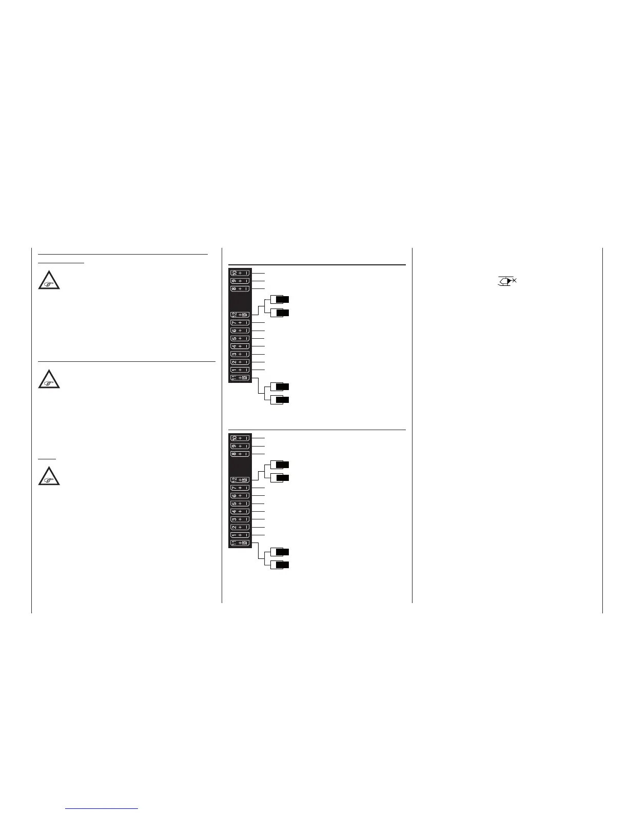
Receiver allocation for helicopter models with
1 to 3 swashplate servos
Receiver power supply
Free or aux. function
Free or aux. function
Tail rotor servo (gyro system)
Roll 1 servo
Pitch-axis 1 servo
Free or speed governor or aux. function
Receiver power supply
Collective pitch or roll 2 or
Pitch-axis 2 servo
Free or aux. function
Throttle servo or speed controller
Gyro gain
Free or aux. function
Free or aux. function
Receiver allocation for helicopter models with
4 swashplate servos
Receiver power supply
Free or aux. function
Free or aux. function
Tail rotor servo (gyro system)
Roll 1 servo
Pitch-axis 1 servo
Free or speed governor or aux. function
Receiver power supply
Roll 2 servo
Pitch-axis 2 servo
Throttle servo or speed controller
Gyro gain
Free or aux. function
Free or aux. function
All menus relevant to helicopter models are marked in
the “program descriptions“ section with a helicopter
symbol …
… so only these menus need to be dealt with to pro-
gram a helicopter model.

 Loading...


