106
Program description - Servo adjustment
normal
reversed
normal
reversed
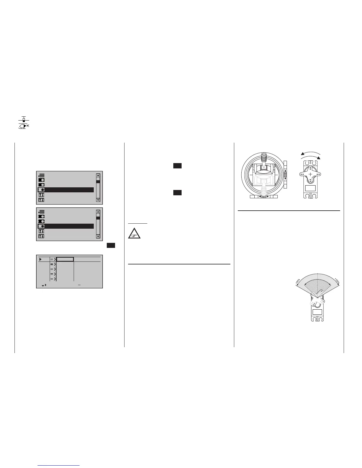
Column 3 “cent.”
The servo midpoint (centre) setting is intended for
adapting a non-standard servo (a servo whose mid-
point position does not correspond to a pulse length of
1.5 ms, i. e. 1500 µs), as well as for minor adjustments,
e. g. for the fine tuning of the neutral position of model
rudders.
Independent of trim levers and any mixer settings,
the neutral point can be shifted in a range of -125 to
+125 % within a maximum servo travel of ±150 %.
Independent of all other trim and mixer settings, this
setting is always based directly on the respective servo.
Note that extreme offsets of
the neutral point can lead
to one-sided restrictions of
servo travel because over-
all travel is limited by both
electronic and mechanical
aspects to a maximum of
±150 %.
A simultaneous tap on the
or keys of the right
four-way button (CLEAR)
will reset the entry field value displayed in inverse video
back to “0 %”.
2. If necessary, use the selection keys of the left
or right four-way button to reach the desired co lumn
then, if desired, move the respective control out of
its midpoint to make an asymmetric setting.
3. Briefly tap the centre SET key of the right four-way
button. The corresponding input field is shown high-
lighted.
4. Use the selection keys of the right four-way button
to set the desired value.
5. Briefly tap the centre SET key of the right four-way
button to complete data entry.
6. A simultaneous tap on the or keys of the
right four-way button (CLEAR) will any setting made
back to its respective default value.
Important:
Servo designation numerals are based on the
respective receiver outputs to which they are
connected, provided that no swapping of
transmitter and/or receiver outputs has been speci-
ed. This means that even a change of stick mode
will not effect the numbering of servos.
Column 2 “rev”
The direction in which a servo turns is adapted to the
practical reality of the given model so that the assembly
of control rods and joints do not need to accommodate
a specific servo rotation direction. Rotation direction is
symbolized by the “=>” and “<=” character combina-
tions. Servo rotation direction must be specified before
making settings for the options which follow below.
A simultaneous tap on the or keys of the right
four-way button (CLEAR) will reset rotation direction
back to “=>”.
This option is available on both transmit-
ter types.
Use the selection keys on the left or
right four-way button to select the »Servo
adjustment« option in the multi-function menu:
Suppress models
Base setup model
Control adjust
Model type
Servo adjustment
Stick mode
Suppress models
Base setup model
Control adjust
Helicopter type
Servo adjustment
Stick mode
Open this menu option with a tap on the centre SET
key of the four-way button pad:
S1
S2
S3
Rev cent
+
trv
0%
0%
0%
100%
100%
100%
100%
100%
100%
0%
0%
100%
100%
100%
100%
S4
S5
This menu is used to set the direction, neutralization,
travel and limit parameters for a given selected servo
exclusively. Begin setting servo parameters in the left
column.
Basic procedure:
1. Select the desired servo, 1 … 8 or 1 … 12, with the
selection keys of the left or right four-way but-
ton.
Servo adjustment
Servo direction, midpoint, travel and limit
S
e
r
v
o
t
r
a
v
e
l
-
1
2
5
%
C
e
n
t
r
e
a
d
j
u
s
t
m
e
n
t
+
1
2
5
%
mc
16 20
Stick movement
Servo direction

 Loading...


