289
Programming examples - Winged models
Integration of an electric drive into the model programming
In5
offset
0%
0%
0%
–––
0%
In6
In7
In8
–––
–––
–––
GL
GL
GL
GL
typ
normal
fr
fr
fr
fr
SEL
A common option in the following examples 1 … 5,
the automatic tracking of the elevator trimming in the
power flight, should also be mentioned at the begin-
ning of this section:
If it becomes apparent after the initial power flights that
the model must be continuously corrected with the
elevator while the motor is switched on, this situation
can be corrected by setting a free mixer and adjusting
it accordingly. For this purpose, switch to the menu …
»Free mixers« (beginning on page 201)
… and program one of the linear mixers, M1 … 8, or
even one of the curve mixers, C9 … 12, from “channel
controlling the motor” according to “EL”, for example:
ty
fr
to
M1
M2
M3
8
EL
M4
M5
??
??
??
??
??
??
??
??
On its second screen page, the required – usually
low – correction value is entered:
L.Mix 1
–100%
Offset
ASY
SYM
8 EL
Mix input
+4%
+4%
Note:
The adjustment of a curve mixer is described
in detail in the section »Channel 1 curve«
starting on page 134.
Example 1
Proportional control usage
If one of these controls is used, the connection is very
simple. Only the motor controller (speed control) has to
be connected to a free servo connection 5 … 12 max.
of the receiver.
Bear in mind that, depending on the model
type and number of aileron and ap servos,
the output 2 + 5 and may be 6 + 7 are already
linked.
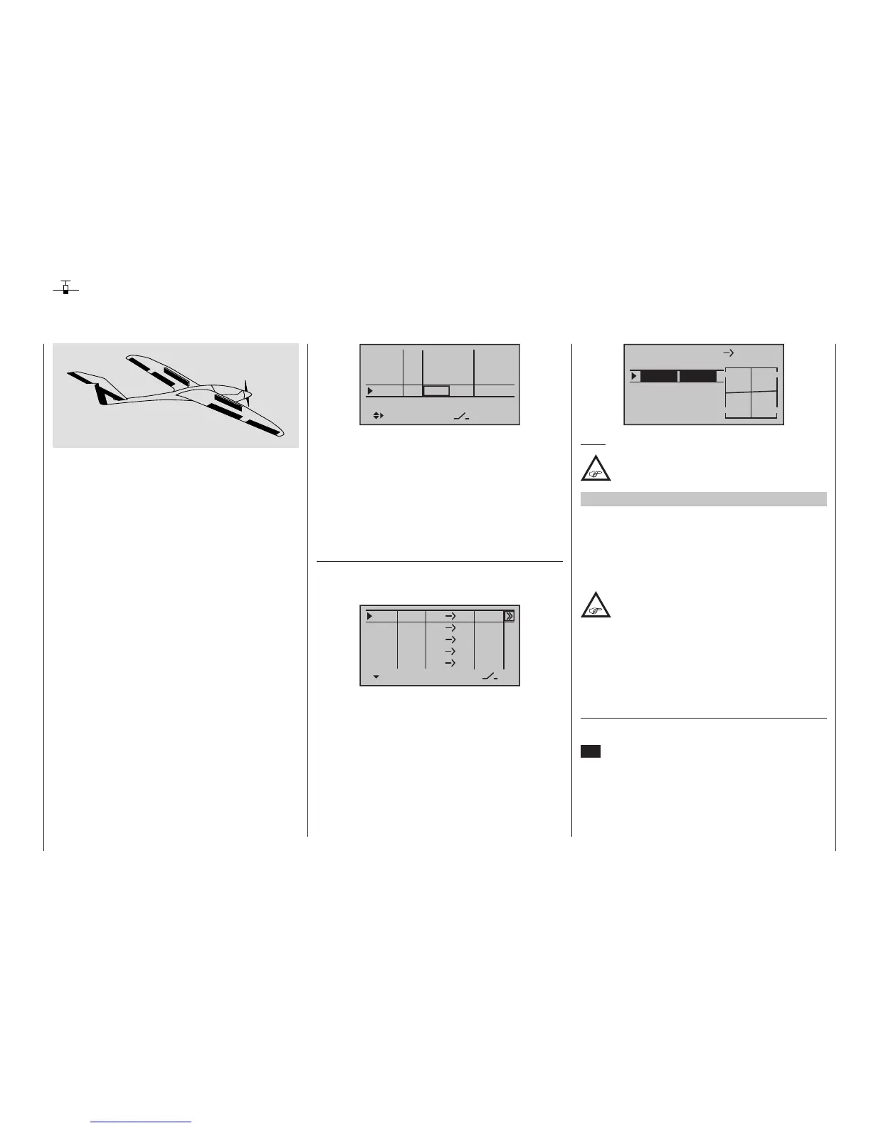
Therefore connect your speed controller to the next
free input and assign the selected input – for example,
“In8” – to one of the transmitter’s proportional controls,
for example the left-side proportional rotary control.
This is done in the menu …
»Control adjust« (page 112)
Select the desired line with the selection keys of
the left or right four-way button. A tap on the centre
SET key of the right four-way button will activate the
“Control assignment”.
An electric drive can be controlled in different ways:
The simplest method to integrate one such drive into
the model programming is with the use of a throttle/
brake stick (C1). However, since this is already speci-
fied for the brake system in the course of the model
programming described above, either the switchable
solution described beginning on page 292 or even the
use of an alternative control is possible.
As a suitable alternative, one of the two 3-position
switches would be better than one of the proportio nals
controls. However, either one of the two side propor-
tional rotary controls are also well suited to activation of
a motor without having to let go of the stick. An alter-
native would also be one of the two-stage switches.
Basically, whatever switch is used should be located
where it is within convenient reach.
Before we turn to the individual examples, it is im-
portant must be noted that all inputs in the »Control
adjust« menu can be selectively programmed as flight-
phase specific (“PH” in the “type” column) or model
memory specific (“GL” in the “type” column)!
However, since the drive should usually be available
depending on the current flight phase, we recommend
leaving the standard default “GL” (“global”) in the “type”
column which your are using.

 Loading...


