198
Program description - Helicopter mixer / Auto-rotation setting
Helicopter mixer
Auto-rotation setting
Auto-rotation permits both full-size and model helicop-
ters to land safely in a crisis, e. g. if the motor should
fail. Moreover, if the tail rotor should fail, cutting the mo-
tor and landing using auto-rotation is also the only pos-
sible way to avoid a high-speed, uncontrollable rotation
around the vertical axis and a resulting catastrophic
crash – which is why a switchover TO the auto-rotation
phase takes place immediately.
Firmware version V1102 and lower
When the switchover to the auto-rotation phase is
made, the Helicopter mixer menu screen changes as
follows:
Pitch
0%
0°
Autorot
–90%
0%
Gyro gain 0%
Thr setting AR
Tailoffset AR
Gyro suppress
Swash rotation
OFFSwash limiter
Firmware version V1102 and higher
Following the trend for electric helicopters, the default
value in the line “AR throttle position” a newly initialized
model memory is now -100%:
Pitch
0%
0°
Autorot
–100%
0%
Gyro 0%
Thr setting AR
Tailoffset AR
Gyro suppress
Swash rotation
OFFSwash limiter
During auto-rotation flight, the main rotor is no longer
driven by the motor but only by its own momentum
and the airflow through the rotor plane during descent.
Since the energy stored by a rotor kept spinning in this
way is rapidly consumed if the helicopter flares, pilots
must not only have experience in hand ling helicopter
models but must also consider carefully how the rel-
evant functions should be configured.
The advanced pilot should therefore practice auto-rota-
tion landings at regular intervals. Not only to be able to
demonstrate mastery of the maneuver at competitions,
but also to ensure the pilot can land the helicopter
undamaged from a great height if the motor should
fail. For this purpose, the program provides a range
of adjustment options designed to help the pilot fly a
motorized model in its unpowered state.
Note that the auto-rotation settings comprise a com-
plete seventh flight phase, which provides access to all
the flight phase-specific configuration options, and to
trims, collective pitch curve settings, etc., in particular.
The following functions have special features not pre-
sent in the powered flight phases:
Pitch (Collective pitch curve (C1 Pitch))
In powered flight, the maximum blade pitch angle is
limited by available motor power. In auto-rotation,
however, it is limited only by the point at which airflow
ceases over the main rotor blades. Greater maximum
collective pitch must therefore be set to ensure suf-
ficient thrust when flaring the helicopter even as rota-
tional speed is falling off. To do so, briefly tap the centre
SET key of the right four-way button to switch to the
“Pitch” graph page and then use the stick to move the
vertical line to point “H”. Start by setting a value that is
about 10 to 20 % greater than your “normal” maximum
value for collective pitch. Initially, however, do NOT set
a value that is considerably greater than for normal
flight, since, if this is done, the behavior of the collective
pitch controls may then be very unfamiliar following the
switchover. Indeed, there is a danger that the pilot will
oversteer during the flare and the model will balloon:
this will case the rotor speed to collapse at a consid-
erable altitude and the model will then crash to the
ground. The value can always be readjusted later after
flying some test auto-rotations.
The minimum value for collective pitch can differ from
that set for normal flight. This depends on the pilot’s
usual style for normal flight. For auto-rotation, how ever,
always set a sufficiently generous minimum value for
collective pitch at point “L” to ensure the model can be
brought out of forward flight at mo derate speed into a
descent at an angle of around 60 … 70 degrees when
collective pitch is reduced to a minimum.
If, like most helicopter pilots, you have used this kind
of setting for normal flight anyway, then this value can
simply be transferred.
If, however, you normally let your model “fall” at a
shallower angle, then you should increase the value at
point “L”, and vice versa.
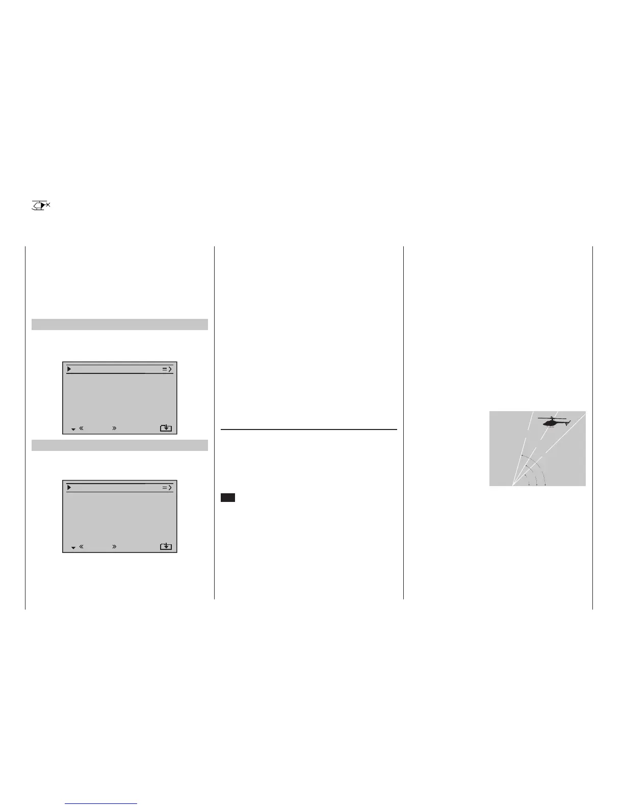
Approach angle for vari-
ous wind conditions
Approach angle
in moderate
wind
no wind
45°
60°
75°
in strong
wind
As a rule, the collective pitch stick itself is not posi-
tioned right at the bottom of its travel for auto-rotation.
Instead, it is typically between the hover position and
the bottom end-point. This offers the pilot an option
for further adjustment, e. g. via pitch inclination through
pitch-axis controls.
The approach can be shortened by pulling back slightly
on the pitch-axis stick and gently reducing pitch or by
extending the approach by pushing forward on the
pitch-axis stick and carefully increasing pitch.

 Loading...


