90
Program description - Base setup models | Helicopter models
“Binding” multiple receivers per model
Multiple receivers per model can be bound if desired,
whereby respective
mc-16 HoTT and mc-20
HoTT programs offer the potential for managing up to
two receivers directly and for dividing up the transmit-
ter’s 8 or 12 control channels (max) in any arrangement
among these receivers under menu control. Refer to
additional details further down in this section. First bind
the receivers individually as described below.
When the system is actually in use, the
only receiver which creates a telemetry
link to the transmitter is either the last
receiver to be bound, or the receiver which you
selected in the “TEL.RCV.” line of the »Telem-
etry« menu, for example:
TELEMETRY
SETTING & DATA VIEW
SENSOR SELECT
RF STATUS VIEW
VOICE TRIGGER
TEL.RCV.
RCV CH1
Any telemetry sensors which may be built into the
model should therefore be connected to this receiver
because the transmitter only receives and evaluates
data from the return channel of the receiver activated
on this line. The second, and all other receivers, oper-
ate in parallel but are fully independent in slave mode.
“Binding” transmitter and receiver
Use the selection keys of the left or right four-way
button to move into the “Module” line:
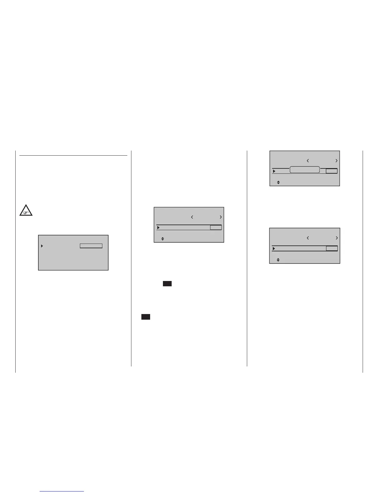
The marker frame will be positioned by default to the
column for the next free binding channel. In the ex-
ample shown in the figure below, the marker frame is
positioned above the column label “BD2” because the
binding channel in the column labelled “BD1” is already
in use by default for the receiver which was delivered
with the set:
1
n/a
bind
BD1
STARLET
BD2
Rcv Ch Map R12
n/a
HoTT
Mod.name
Stick mode
module
Base setup model
If already off, now switch the receiver on:
Receiver GR-16 and GR-24
The red LED on the receiver will blink..
Press and hold the SET button on the receiver while
the LED continues to blink red for about 3 seconds,
then begins to blink red/green for about another 3
seconds. The SET button on the receiver can now
be released. As long as this LED blinks red/green, the
receiver is in bind mode.
Now, within this 3 second period, start the so-called
“receiver binding” process for the receiver to the cur-
rently active model memory with a brief tap on the cen-
tre SET key of the right four-way button. At this time,
the screen’s display will blend in a message window for
the duration of the “binding” process.
1
n/a
bind
BD1
STARLET
BD2
Rcv Ch Map R12
n/a
HoTT
Mod.name
Stick mode
module
Base setup model
Finding...
If the receiver’s LED, again blinking red, changes within
about 10 seconds to continuous illumination in green,
the binding process has been successfully completed.
Your model-memory to receiver combination is now
operationally ready. At this time the screen will now
display “ bind “ (bound) instead of “n/a” (not attached),
for example:
1
bind
bind
BD1
STARLET
BD2
Rcv Ch Map R12
R08
HoTT
Mod.name
Stick mode
module
Base setup model
On the other hand, should the LED on the receiver
blink red for longer than about 10 seconds, the binding
process has failed. In this case the screen will continue
to show the status as “n/a”. If this should happen,
try changing the position of antennas then repeat the
entire procedure.
Receiver GR-12L
At the receiver, the red LED lights. Press and hold the
SET button on the receiver until the red LED goes out
after about 3 seconds for a further 3 seconds. You can
now release the SET button on the receiver. As long
as the LED is off, the receiver is in bind mode. Start
now-as described above-within these 3 s to bind the
receiver to the current model memory. If the LED of the
receiver is still dark and the display in the transmitter
changes to “b”, the binding process has been complet-
ed successfully. However, the red LED will light up red
again at the receiver, the binding process has failed. At

 Loading...


