320
Programming examples - Helicopter models
Helicopter models
However, we do not want to dispense entirely with the
enhancement possibilities: Therefore, after the basic
description, you will fi nd adjustment information for
the gyro effect, the speed regulators and for the fl ight-
phase programming.
Note:
If you are not interested in the combustion
helicopter described here, but a electric
helicopter, please continue reading anyhow!
With the exception of the omitted idle settings, you
can practically adopt most of the settings described in
the following unchanged.
In the scope of the initial commissioning of a new
transmitter, in the selection menu …
»Basic settings« (page 266)
Battery type
Battery warning
Touch Sense
Top LCD Contrast
Lith.
Display light
2
3.60V
0
unlim.
Basic settings
Vario Vol
Beeps Vol
Power-on beep
yes
Power on warn.
unlim
BT Headset
OFF
0/0
ID PAIR
OFF
BT Volume
8
Voice Vol –––5
–––7
–––7
Own
Stick mode 1
Modulation HoTT
DSC Output
PPM10
Pitch min back
Bottom LCD Contr.
0
SEL
SEL
fr
fr
fr
DATA sel Telemetry
… some basic information should be entered. This
serves various purposes:
The fi rst three lines of this menu can be used to indi-
vidually regulate, in increments between 0 and 10, the
volume of voice and signal output emitted via the built-
in loudspeakers or the transmitter’s headset connec-
tor. The fourth line of this menu is used to record the
transmitter owner’s name. Select the characters for this
from an extensive character list on the second display
screen, which can be reached via the symbol with
a brief tap on the centre SET key of the right touch
pad:
!"#$%&’()�+,–./0123
456789:;
Owner
H-J Sandb
FGHIJKLMNOPQRSTUVWX
YZ[¥]^_`ab cdefghijk
?@ AB CDE
The pre-set for “Stick mode” can be selected accord-
ing to the criteria described on page 267.
The same applies to the pre-sets for “Modulation”
and “DSC Output”, page 268.
The pre-set for “Pitch min” is a matter of personal
control habits, page 104.
The pre-sets established here for “Stick mode”, “Mod-
ulation”, “DSC Output” and “Pitch forward/back”
will be initially adopted when a new model memory is
created but they can also be freely changed within a
given model memory location to any other available
option.
The settings in the “Top/Bottom LCD Contrast” lines
determine the legibility of the given displays under poor
light conditions and the setting in the “Display light”
line determines how long display lighting remains illumi-
nated after the transmitter is switched on without any
actuation of a control afterward or after the last control
actuation.
With this programming example, you must have al-
ready covered the description of the individual menus
and you must be familiar with the use of the transmitter.
In addition, the helicopter’s mechanical construction
should correspond exactly to the corresponding man-
ual. The electronic capabilities of the transmitter should
by no means be used to straighten out rough mechani-
cal imprecision.
As is often the case in life, there are also various
ways and possibilities to achieve a specifi c goal when
programming the
mc-16 HoTT or mc-20 HoTT
transmitter. The following example should provide you
with a clearer structure for logical programming. If there
are multiple possibilities, the simplest and most clearly
arranged solutions are recommended fi rst. In order for
the helicopter to function faultlessly later on, you are,
of course, free to try out other solutions which may be
better for you.
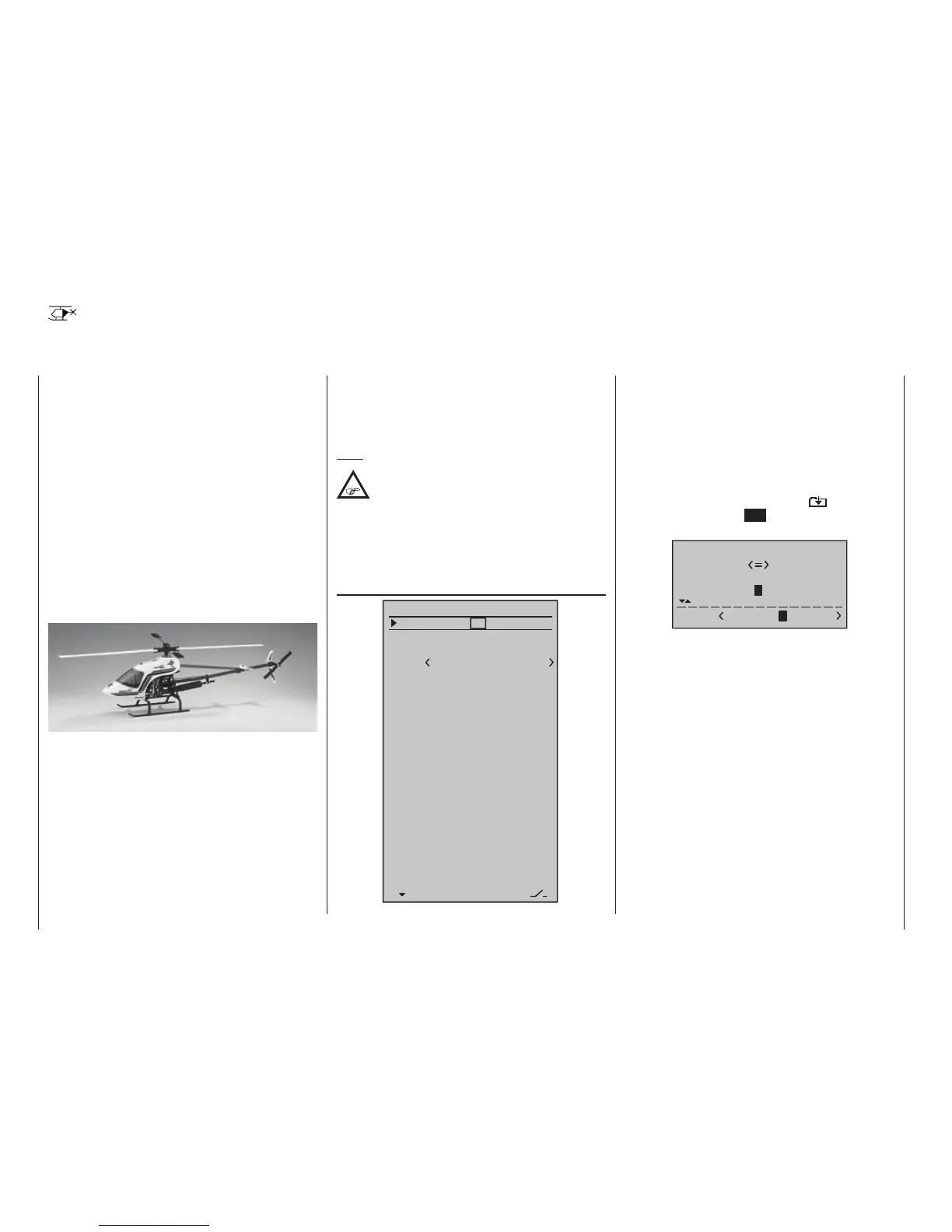
The programming example is based on the clockwise-
rotating STARLET 50 helicopter from Graupner with
three pivot points each offset 120 ° of the swashplate
type “3Sv(2 Roll)”, beginner adjustment without in-
creased throttle curve; without heading-lock gyro sys-
tem and without transmitter-side gyro infl uence of the
“normal operating mode” and without speed regulator.
This simple program was also consciously selected
to demonstrate that a helicopter which fl ies really well
can also be attained with relatively little (programming)
effort.

 Loading...


