162
Program description - Flight phase timers
Fl. phase timers
Selecting and setting
This option is available on both transmit-
ter types.
A description of how timers are assigned
to a flight phase has already been provided
in the text for the »Phase settings« menu, page 148
and 152. The same section has also described the
properties of “Time1” and “Time2”. This section now
proceeds to describe “Timer 1, 2 and 3” and the “lap
counter/time table” timer variants.
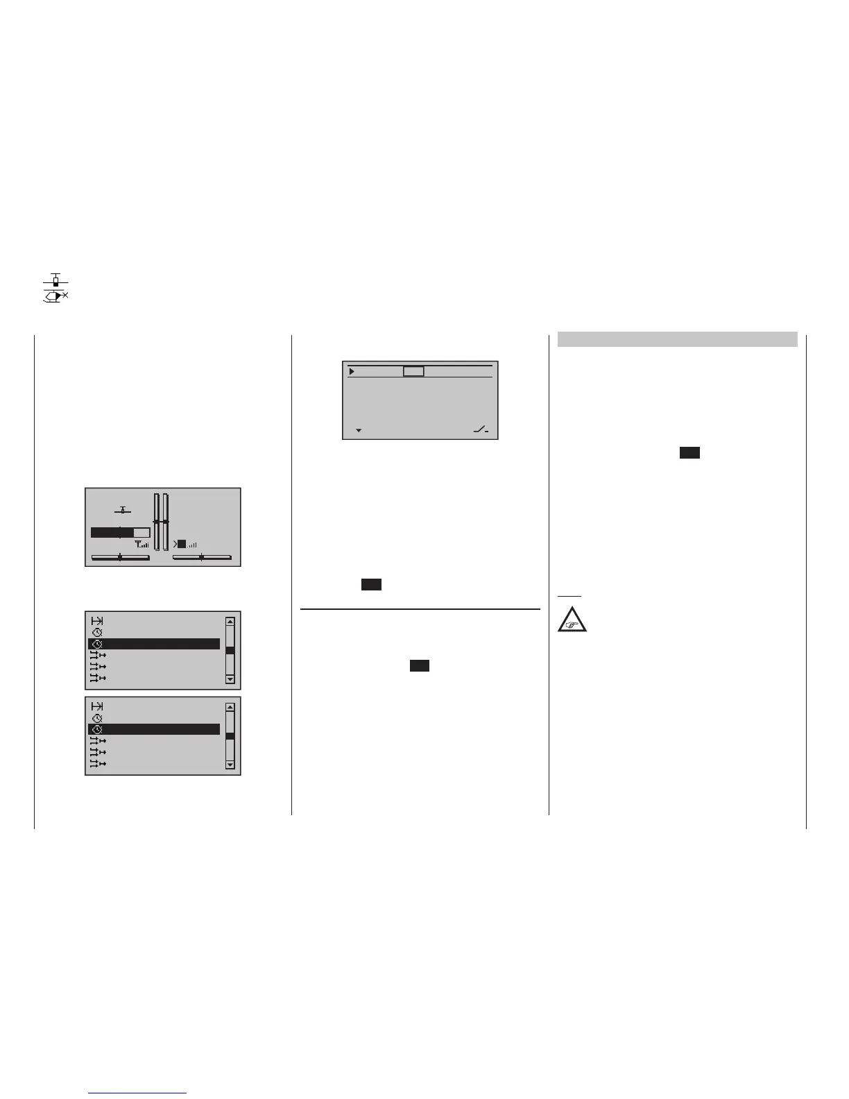
The additional, flight phase-specific timer selected is
displayed on the basic display underneath the “centre”
timer, as shown below:
GRAUBELE
#01
2:22h
Stp
Flt
«Speed »
K78
0:00
0:00
5.5V
3.9V
HoTT
M
Clk1 0:00
Use the selection keys of the left or right four-way but-
ton to scroll to the »Fl. phase timer« menu option in
the Multi-function menu:
Non-delayed chan
Timers (general)
Wing mixers
Free mixers
MIX active/phase
Fl. phase timers
Non-delayed chan
Timers (general)
Helicopter mixer
Free mixers
MIX active/phase
Fl. phase timers
On this menu you can now program “Clks 1 … 3” as
stopwatches (i. e. timers that run forward) or as count-
down/alarm timers (i. e. timers that run backwards). You
can assign any switch to these timers, and the same is
true of the “lap counter/timetable” timer:
Timer1
Timer2
Timer3
Lap time/Tim tab
SEL
–––
0:00
0:00
0:00
Lap Display
0s
0s
0s
–––
–––
–––
–––
SEL
The flight phase timers “Timer 1 … 3” and the
“Time1”/”Time2” timers (described in the »Phase
settings« section, pp. 148 and 152) run only in the
flight phase to which they have been assigned. They
are also shown as appropriate on the basic display.
During other flight phases they are stopped (and hid-
den) and the assigned stop/start switch then has no
effect.
The lap counter, once started, continues to run through
changes of phase (as discussed further below), how-
ever, although it can be stopped during any flight phase
via the centre ESC key of the left four-way button.
Clks 1, 2 and 3
These timers are started and stopped via a switch or
control switch. To do so, first use the selection keys
to select the appropriate column via the switch icon at
the bottom right. Then set the switch that you want by
briefly tapping the centre SET key of the right four-way
button, as described in the section “Physical control,
switch and control switch assignments“ on page 60.
Here, too, a control switch offers you the option of
activating the timer via one of the sticks or proportional
controls. The switching point along the transmitter
control travel is set on the »Control switch« menu,
page 141.
Remember that the timer switches also remain active in
programming mode.
Switching between “forwards” and “backwards”
Stopwatch mode (timer runs forwards)
In this mode, the timer starts at the initial value “0:00”
(min:sec) when you operate the assigned switch. If it
reaches the maximum time of 179 min. and 59 s, it will
re-start at “0:00”.
“Countdown” (timer runs backwards)
Following the activation of the corresponding value
fields (by tapping the centre SET key of the right four-
way button), if a time in minutes (maximum 179 min)
and/or a time in seconds (maximum 59 s, right field) is
set, then the timers will run backwards from this initial
value following the activation of the assigned switch
(see section “Physical control, switch and control
switch assignments“ on page 60), i. e. a “count-
down” function will apply. Once the timer reaches
zero it does not stop, however, but continues to run
(highlighted) so you can read off the time elapsed after
reaching zero.
Note:
Timers that are running backwards are shown
on the basic display with a ashing colon (:)
between the minutes and the seconds elds.
A simultaneous tap on the or keys of the right
four-way button (CLEAR) will reset entry values in the
currently active field back to zero.
mc
16 20

 Loading...


