163
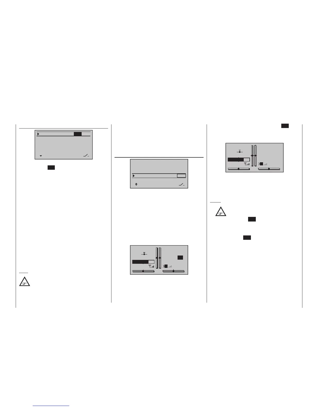
Program description - Flight phase timers
“Alarm” timer
SEL
–––
0:00
0:00
0:00
0s
0s
–––
–––
–––
–––
SEL
0s
Timer1
Timer2
Timer3
Lap time/Tim tab
Lap Display
The input field in the “Alarm” column is activated with a
tap on the centre SET key of the right four-way but-
ton. In this field, use the selection keys on the left or
right four-way button to define a time between 5 and
90 seconds (in 5-second increments) before zero is
reached: at this point an audible signal will be emitted,
which eliminates the need for you to check the screen
continually during the flight.
Audible signal sequence
30 s before zero: Triple beep
Single beep every two seconds
20 s before zero: Double beep
Single beep every two seconds
10 s before zero: Single beep
Single beep every second
5 s before zero: every second a single beep at a
higher frequency
zero: longer beep signal and changeover
of display presentation to inverse
video
A simultaneous tap on the or keys of the right
four-way button (CLEAR) will reset entry values en-
tered in the currently active field to “0 s”.
Note:
If timer functionality has been changed at any
point, then the new changes to settings are
made active only after the timer(s) have been
stopped on the basic display then making a simulta-
neous tap on the or keys of the right four-
way button (CLEAR) to reset them.
Like the two standard timers positioned above it, this
third, phase-specific timer is reset to its starting value
with a simultaneous tap on the or keys of
the right four-way button (CLEAR). It is stopped in all
flight phases at the same time, even if it has not been
stopped separately in the other flight phases.
Lap counter/timetable
SEL
–––
0:00
0:00
0:00
0s
0s
–––
–––
–––
–––
SEL
0s
Timer1
Timer2
Timer3
Lap time/Tim tab
Lap Display
On the “Lap time/tim tab” line, assign a switch only as
described in the section “Physical control, switch and
control switch assignments“ on page 60. Preferably,
make use of a momentary switch, which are included
as standard equipment only in the switch panels of the
mc-20 HoTT transmitters. The lap count is incre-
mented each time by one lap while simultaneously (and
automatically) the lap time elapsed during this lap is
stopped (and recorded). This momentary switch simul-
taneously starts the stopwatch for the next lap. As the
timer is triggered, the lap or switch impulse counter is
shown highlighted:
GRAUBELE
#01
2:22h
Stp
Flt
«Speed »
K78
0:00
0:00
5.5V
3.9V
0:00.0
M
Lap
2:33.4
11
“Time1” and “Time2” operate in the same manner; for
more details please read the section on the »Phase
settings« menu option on page 148 or 152.
Up to 99 lap times can be recorded and accessed,
each with a maximum duration of 99 minutes and 59.9
seconds.
To stop the timer in question, tap the centre ESC key
of the left four-way button on the basic display after the
flight is over. The lap or switch impulse counter is now
shown in “normal” mode:
GRAUBELE
#01
2:24h
Stp
Flt
«Speed »
K78
0:00
0:00
5.5V
3.9V
0:00.0
M
Lap
4:33.2
22
A simultaneously tap on the or keys of the
right four-way button at the same time (CLEAR) will
reset the counter to “00” and deletes the stored
times. However, the timers must have been stopped
beforethis.
Notes:
•
If you have selected a normal switch to
operate the lap counter, take care to en-
sure that this switch is set to “OFF” before
touching the centre ESC key of the left four-way
button.
• If you should forget to switch off the lap counter in
a phase which is now not currently active, simply
touch the centre ESC key of the left four-way but-
ton.
To swap between the basic display and the “LapDis-
play” …

 Loading...


