292
Programming examples - Winged models
Tail type
Motor at C1
Normal
Aile/flaps
2AIL
Model type
Brake Off In 1–90%
SEL
front
STO
This idle path ensures that all brake settings remain at
“neutral”, even with minor deviations from the limit of
the brake flap control. At the same time, the effective
control path is automatically spread to 100 %.
For this reason, in the next step it must be ensured
that the influence of the C1 stick on the motor can be
influenced. For this purpose, switch to the menu …
»Phase settings« (page 148)
… and assign a meaningful name, such as “Normal”,
from the list for “Phase 1” after activation of the selec-
tion field in the “Name” column. The asterisk in the sec-
ond column indicates which phase is currently active.
As long as no phase switch has been assigned, this is
always Phase1. “Phase 2” can be given, appropriate
to the example, the name «Landing».
In the “ph.Tim” column you can assign a so-called
flight phase timer for the measurement of the motor
running time and/or the gliding times as necessary for
each phase. You could, for example, assign one of the
“Timers 1 … 3” to the “Normal” flight phase in order to
measure the total motor runtime via the C1 stick:
Pha1
Pha2
Pha3
Name ph.Tim
Pha4
Pha5
normal
Strecke
–
–
–
–
Clk 1
Landing
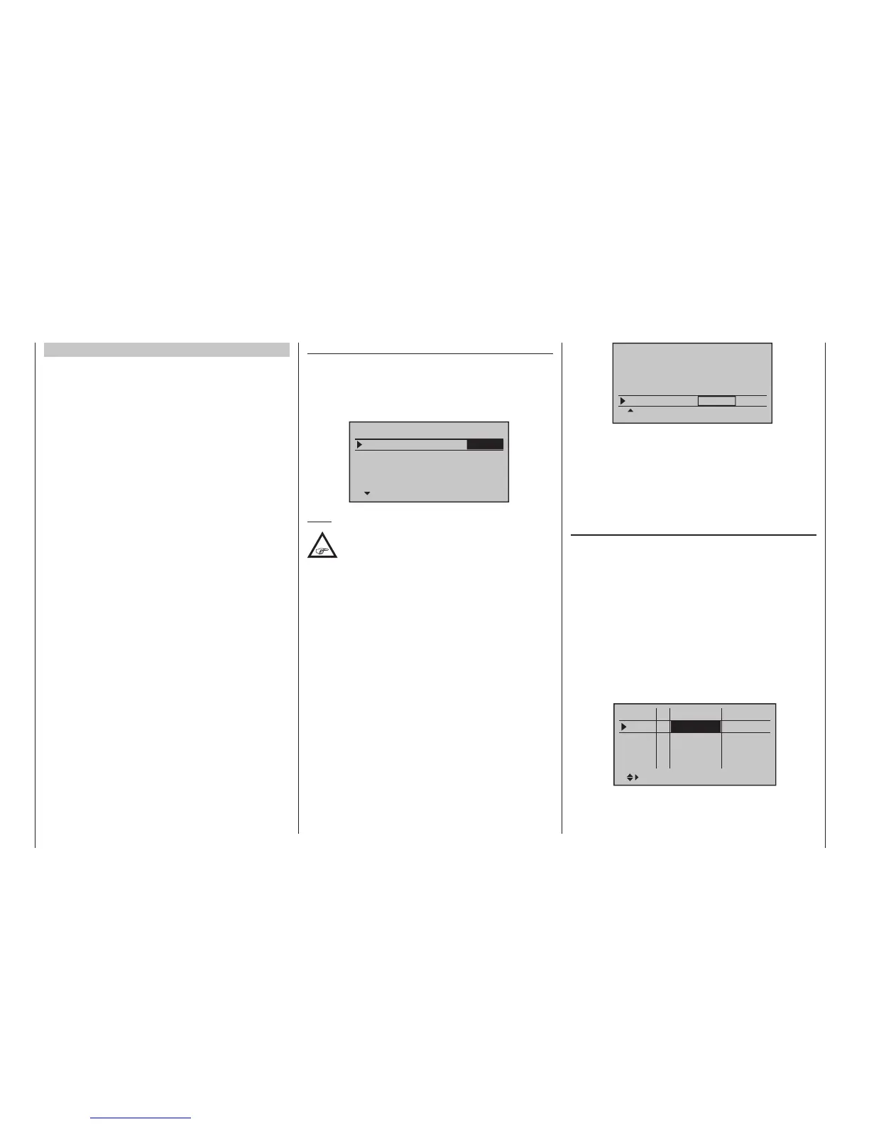
»Model type« (page 98)
Here you first specify in the “motor” line whether the
throttle minimum position (= Motor “OFF” position)
should be at the “front” or “back” – as already dis-
cussed: In the following programming example, “Motor
OFF” and “Brake OFF” are combined at “front”:
Tail type
Motor at C1
Normal
Aile/flaps
1AIL
Model type
Brake Off In 1+100%
SEL
front
Note:
With the selection of “Throttle min front/back”
the trimming will then only have an effect in
the “idle” direction of the motor and is not the
same as with the “none” entry, having the same effect
at every position of the C1 stick. Since the C1 trim-
ming is not normally used with electric drives, how-
ever, this has no further relevance.
You adjust the “Tail type” according to your model, in
this case “normal”.
In the “Aileron/flaps” line you enter the correct number
of aileron and flap servos – in this example “2AIL”.
In the last line you leave the standard entries for the se-
lection of “Brake retracted = front”. On the other hand,
if the preference is for “Brake retracted = back”, select
the “Brake offset” line and define the offset point – as
described on page 100 – as “back”. In the process,
if the offset point is not placed completely at the end of
the control travel, the remainder of the travel is “idle” up
to this limit.
Control E-motor and crow alternately with C1 stick
Example 4
Before we discuss the programming of this fourth
example or turn to the expansion of the previously
described basic programming, a few words should be
said about the position of the throttle/brake stick with
“Motor OFF” or “Brake OFF”. Normally the C1 con-
trol stick is moved forward for the throttle control and
backward for the extension of the brake. However, if
for this type of “traditional” assignment, for example, a
switchover of the brake system is to take place for the
“Motor OFF” condition (stick “back”) then a switchover
to “full brake” would take place immediately after the
pre-set switchover time specified in the »Phase set-
tings« menu, and the opposite will take place when
“brakes retracted” is switched over to propulsion caus-
ing the motor to switch over to “full power” within this
time range …
A “glider pilot” can make the best of this “Emergen-
cy” – normally with “brake retracted = front” – by switch-
ing to motor “ON” only if necessary so that power
decreases, if applicable (and hopefully not forgetting
to push the C1 stick “forward” again when switching
back). A typical “motor pilot”, on the other hand, op-
erates in the opposite manner, only switching to the
brake if necessary, etc. You can also combine the “Zero
point” of both systems to avoid confusion, whereby a
“glider pilot” would tend prefer the “front” and a “motor
pilot”, on the other hand”, would likely prefer the “rear”.
Whichever the case may be, the
mc-16 HoTT and
mc-20 HoTT transmitters permits both variants. In
the following text, however, the combination of the two
“OFF” positions to “front” is assumed. However, if you
have a different preference, it is not a problem: The only
difference from the described version lies in the logical
selection of “Throttle min rear/front” and, if applicable,
of a corresponding brake offset in the menu …

 Loading...


