293
Programming examples - Winged models
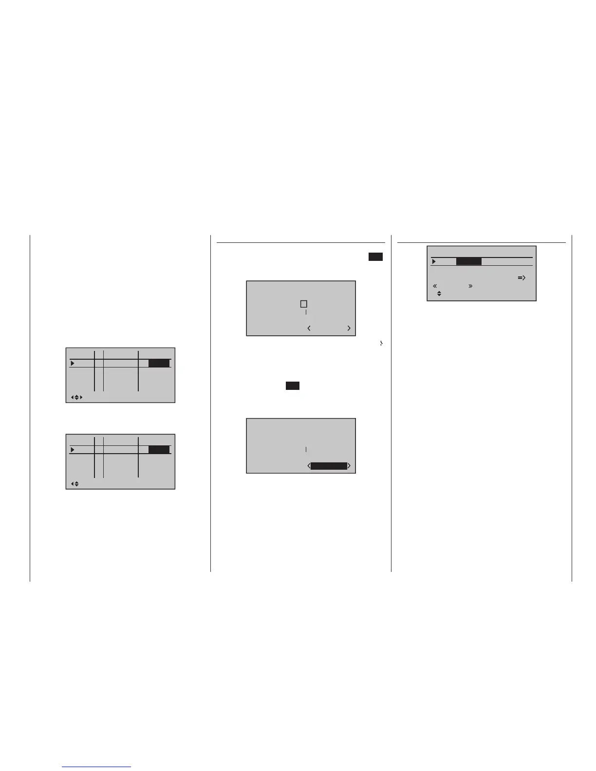
»Brake settings« (page 180)
Elevat curve
Brake settings
AILE
Crow
D.red 0%
0%
0%
0%
0%
WK WK2
Landing
0%
… of the »Wing mixers« menu, set the desired throw
of the ailerons by actuation of the C1 stick (“brake”)
upward. Then, if applicable, switch to the “FL” column
in order to specify the desired through of the flaps with
C1 actuation downward (hidden in the figure above).
This flap position is referred to as “Crow position” or
“Butterfly; see also page 180.
In the line “D.red” (differentiation reduction), enter a
value which corresponds to the value entered or want
to enter on the first page of the »Wing mixers« menu
in the “Aile.diff.” line.
With the “Elevat curve” mixer the normally occurring
“Upward tilting” of the model on the raising of the ailer-
ons can be automatically suppressed. The sui table cor-
rection values for the respective value must be tested
out through flight. Set this mixer so that the flight speed
of the model does not change too much with the brake
system extended in comparison with the “normal” flight
speed. Otherwise, there is the risk, among other things,
that the model plunges when the brake system is
retracted, e. g. for the extension of a landing approach
which is too short.
»Phase assignment« (page 154)
Select the switch symbol under “C” with one of the
selection keys. Following a brief tap on the centre SET
key of the right four-way button, actuate the desired
switch, e.g “2”.
Phase assignment
A B
C D E F
1 normal
2
prior
combi
Both switch positions, in other words ON (I) and OFF(
), are initially assigned at the bottom right of the display
to phase «1 Normal». Select this value field with one of
the selection keys then activate the phase selection list
that was set up in the »Phase settings« menu with a
brief tap on the centre SET key of the right four-way
button. For example, you name the phase for the front
switch position “normal” and “landing” for the rear posi-
tion (or vice versa):
Phase assignment
A B
C D E F
2
prior
combi
2Landing
These phase names then appear in all flight-phase de-
pendent menus and, of course, also in the base screen
of the transmitter.
Now switch to the «Landing» flight phase and in the
“Crow” line of the sub-menu …
Then the timer is controlled through a corresponding
control switch to be defined on the C1 stick. As soon
as you switch to the “Landing” flight phase, this flight
phase timer is automatically stopped and hidden in the
base screen. More about this can be found on page
162.
Now move the marker frame over the “ph.Tim” col-
umn to the “Motor” column to the right. Here you can
decide with “yes/no” in which phase the motor is con-
trolled by the throttle/brake stick and the brake system
to be adjusted in the “Brake settings” sub-menu of the
»Wing mixers« menu should be shut off (= “yes”) and
vice versa (= “no”):
Pha1
Pha2
Pha3
Name motor
Pha4
Pha5
normal
Strecke
–
–
–
–
yes
Landing
no
Now move the marker frame once more to the right
and enter an appropriate switching time after activation
of the value field of the “Sw.Time” column; for example:
Pha1
Pha2
Pha3
Name Sw.time
Pha4
Pha5
normal
Strecke
–
–
–
–
Landing
1.1s
0.1s
0.1s
0.1s
1.1s
Then you must assigned these two flight phases to
a switch with which you can switch between the two
flight phases during the flight. In this case, a single
switch is sufficient. It should be easy to reach, how-
ever, so that you can still switch between “motor” and
“brake” during a landing approach, for example, with-
out having to release a stick.
The assignment of the selected switch takes place in
the menu …

 Loading...


