144
Program description - Logical switches
Logical switches
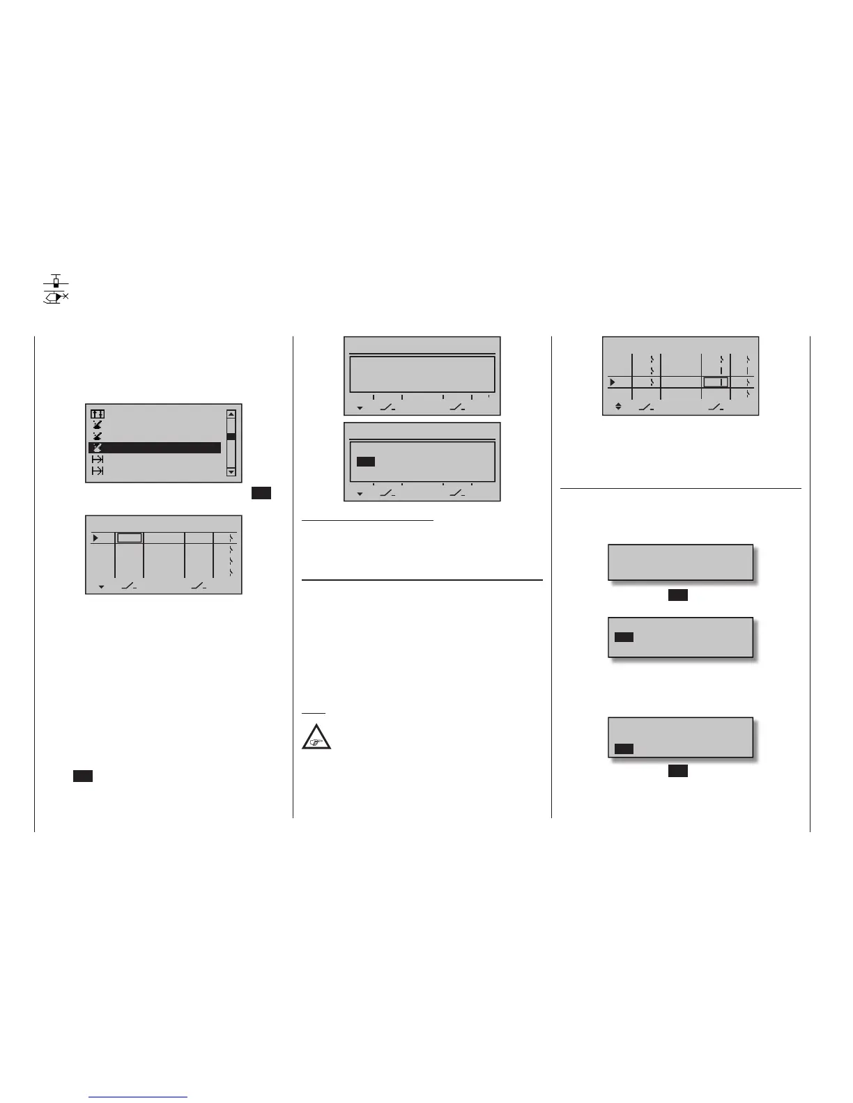
Programming logical switches
This option is available on the mc-20
HoTT transmitter only.
Use the selection keys of the left or right
four-way button to scroll to the »Logical
switches« menu option in the Multi-function menu:
Switch display
Channel 1 curve
Phase settings
Phase assignment
Control switch
Logical switch
Open this menu option with a tap on the centre SET
key of the right four-way button:
AND
AND
AND
L1
L2
L3
–––
L4
Logical switch
AND
–––
–––
–––
SEL
L1
L2
L3
L4
–––
–––
–––
–––
This function, which is available only on the mc-20
HoTT, can be used to link together two switches, con-
trol switches and / or logical switches, or any combina-
tion of the above, in an “AND” or “OR” arrangement. A
total of eight logical switches “L1 … L8” can be pro-
grammed in every model memory.
The result of such a logical switch function – shown in
the display’s rightmost column – can be used as an-
other switch function. Allocation of a switch to a logical
function is done in the familiar manner in the columns
labelled by the two switch symbols, as described in
the section “Physical control, switch and control switch
assignments” on page 60. That is, by moving the
respective switch from OFF to ON or, after a tap on the
centre SET key of the right four-way button, by select-
ing one of the expanded switches with the selection
keys:
AND
AND
AND
L1
L2
L3
–––
L4
Logical switch
AND
–––
–––
–––
SEL
L1
L2
L3
L4
–––
–––
–––
–––
Move desired switch
to ON position
(ext. switch: SET)
AND
AND
AND
L1
L2
L3
–––
L4
Logical switch
AND
–––
–––
–––
SEL
L1
L2
L3
L4
–––
–––
–––
–––
Control/Logic/fix sw
C2 C3 C4 FX
FXi L1 L2 L3 L4
C1
Potential applications for this:
Multiple functions, which are normally independent of
one another, are to be put into a de ned state by way
of an »Emergency switch«.
“AND” / “OR”
Once a given value fi eld has been activated in the col-
umn labelled SEL, the “AND” and “OR” logic operator
can be selected with the selection keys.
• “AND” function
The logical switch is only closed when both input
switches are closed.
• “OR” function
The logical switch is closed when at least one of the
input switches is closed.
Note:
The difference between AND and OR logic
switches is made clear by the settings and
input states of the display gure below.
OR
AND
AND
L1
L2
L3
–––
L4
Logical switch
AND
4
2
L1
L2
L3
L4
–––
3
1
SEL
L1
L2
“L3” is only closed when both the “L1” and “L2”
switches are closed. This means that both switches,
1 and 2, must be closed and, at the same time, either
3 or 4.
Application
In order to make these logical switches usable, they
can be specifi ed in those menus which use switches
by calling them up via the additional “expanded switch-
es” selection menu:
Move desired switch
to ON position
(ext. switch: SET)
A brief tap on the centre SET key of the right four-way
button will afford access to the expanded switches:
Control/Logic/fix sw
C2 C3 C4 FX
FXi L1 L2 L3 L4
C1
Now use the selection keys to pick the desired control
switch “C1 … C4”, fi xed switch “FX” or logical switch
“L1 … L8” or the respected inverted switch “C1i …
C4i”, “FXi” or “L1i … L8i”, for example, “L3i”:
Control/Logic/fix sw
C2i C3i C4i L1i L2i
L4i
L3i
L5i L6i L7i
A brief tap on the centre SET key of the right four-way
button will adopt the selected switch into the menu:
mc
16 20

 Loading...


