143
Program description - Control switches
Combining a control switch with a switch
The control switch can be overridden by a further
switch, so that e. g. in certain fl ight situations the func-
tion to be triggered can be activated independently of
the control position and thus the position of the control
switch.
Change to the value fi eld in the 5th column, the column
above the rightmost switch symbol. In the simplest
case, select one of the switches mounted in the two
switch panels, as described in the section “Physi-
cal control, switch and control switch assignments”
on page 60. The number of this switch, e. g. “10”,
appears on the display in the next-to-the last column
at the right, together with a switch icon indicating the
switch’s current state.
SEL
0%
0%
0%
C1
C2
C3
–––
C4
Control switch
Lv2
Gb1
+85%
STO
–––
–––
SEL
10
While this switch is open, the “C1” control switch is ac-
tive, i. e. it triggers at the switching point; if the switch
is closed, the control switch now remains permanently
closed as well, independently of the control position
and switching direction:
SEL
0%
0%
0%
C1
C2
C3
–––
C4
Control switch
Lv2
Gb1
+85%
STO
–––
–––
SEL
10
Combining two control switches
For more complex applications, however, it can prove
necessary to override this control switch with a second
control switch.
Example:
Control switch “C1” will now be assigned to control
function 3 (= control 3) instead of its previous assign-
ment “Lever2”. The switching point is at its centre
point, i. e. at 0 %. The switch chosen in the next-to-
the-last right column is “C2” from the list of expanded
switches. This “C2” control switch will now be al-
located in its own line to the right proportional slider
“Slide2”, whose switch-point is +50 %:
SEL
0%
0%
+50%
C1
C2
C3
–––
C4
Control switch
STO
–––
–––
Cn3
C2
Sl2
0%
SEL
The switching directions indicated in the fourth col-
umn from the left will now show control switch “C2” as
being closed as long as stick (control 3) and/or “Slide
2” are located on the other side of their switch-points.
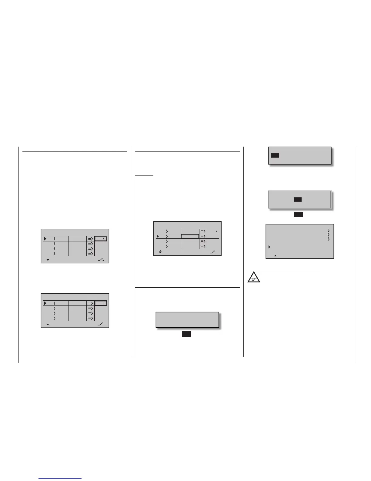
Application
In order to make these control switches usable, they
can be specifi ed in those menus which use switches
by calling them up via the additional “expanded switch-
es” selection menu:
Move desired switch
to ON position
(ext. switch: SET)
A brief tap on the centre SET key of the right four-way
button will afford access to the expanded switches:
Control/Logic/fix sw
C2 C3 C4 FX
FXi L1 L2 L3 L4
C1
Now use the selection keys to pick the desired control
switch “C1 … C4”, fi xed switch “FX” or logical switch
“L1 … L8” or the respected inverted switch “C1i …
C4i”, “FXi” or “L1i … L8i”, for example, “C3”:
Control/Logic/fix sw
C2 C4 FX
FXi L1 L2 L3 L4
C1
C3
A brief tap on the centre SET key of the right four-way
button will adopt the selected switch into the menu:
8
7
15
VOICE TRIGGER
REPEAT 10SEC
TRIG
TRANSMITTER
RECEIVER
VARIO
AUTO
Note regarding the inverted switches:
If you select an inverted switch during the
assignment process – e. g. “G3i” instead of
“G3” – the only difference is that the switching
direction is simply reversed, i. e. if a particular switch
is intended to activate a function – e. g. a mixer – when
turned on, then the same switch with the “i” suf x (=
inverted) activates this function when it is turned off.
Typical applications might be a need for one and the
same switch to turn one function on, and simultane-
ously to turn a second function off, and vice versa.
These facilities, especially when used in conjunction
with logical switches (described in the following
section) can be exploited to cope with extremely
complex switching systems.

 Loading...


