291
Programming examples - Winged models
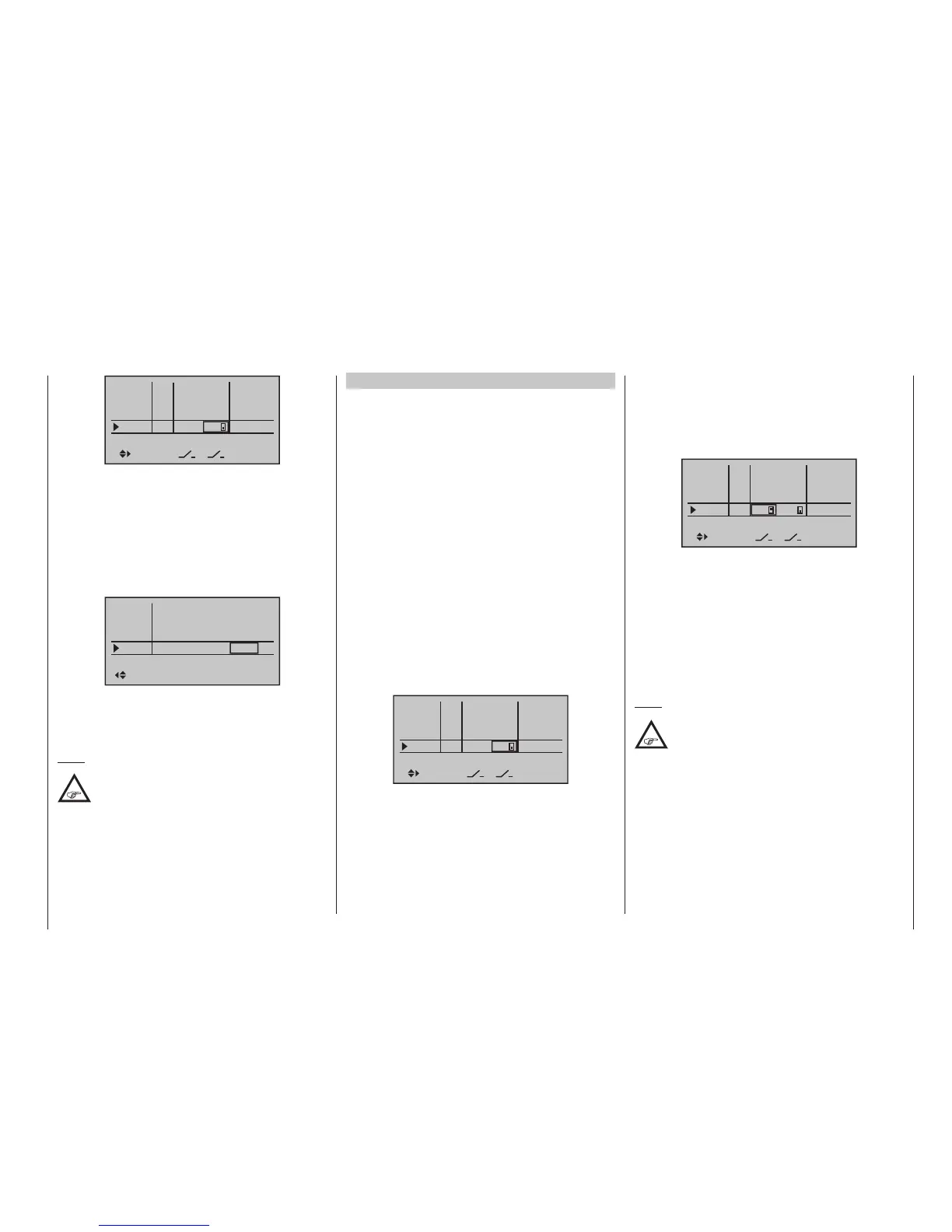
In5
offset
0%
0%
0%
–––
0%
In6
In7
In8
–––
–––
–––
GL
GL
GL
GL
typ
normal
fr
fr
fr
2
Here again – as already mentioned earlier in this sec-
tion – leave the standard default “GL” in the “Typ” col-
umn.
The setting of the appropriate control travel for the
motor control (speed control) is made in the “- trv+”
column. If the motor should up gently with the use of
a motor control (speed control), an appropriate delay
time can be set – as described in Example 1 – in the
“-time +” column:
In5
– time +
0.0s
0.0s
0.0s
1.1s
In6
In7
In8
0.0s
0.0s
0.0s
0.0s
normal
All other settings – as already mentioned earlier in the
example – are made analogous to Example1. There-
fore, the same comments and recommendations also
apply.
Note:
No delay is entered on the “OFF” side, so that
the drive can be switched off instantly at any
time. This does not additionally stress the
drive, because it merely “runs down”.
Example 3
3-way switch usage
This variant realizes a three-stage speed setting, such
as Motor OFF, “half” and full power.
A corresponding motor control (speed control) is re-
quired on the receiver side.
The required settings are basically the same as those
described under Example 1 and 2. Therefore, the same
comments and recommendations also apply.
Apart from the infinitely variable motor control under
Example 1 and the three-stage motor control in this ex-
ample, the selection of the operating element only has
an effect on the type of clock control, see page 296,
and the nature of the assignment.
Here again – as already mentioned earlier in this sec-
tion – leave the standard default “GL” in the “type”
column.
Put the desired 3-way switch into its middle position
then activate the “Switch assignment” above the col-
umn with the switch symbol, as described on page
60. Now put the selected 3-way switch forward, out
of its middle position:
In5
offset
0%
0%
0%
–––
0%
In6
In7
In8
–––
–––
–––
GL
GL
GL
GL
typ
normal
fr
fr
fr
3
Now put the activated switch from its forward position
back into its middle position.
Now move the marker frame to the left and into the
column above the column now labelled with a second
switch symbol instead of the previous label SEL. Re-
activate the “Switch assignment” for this column then
move the 3-way switch out of its middle position to-
ward the rear:
In5
offset
0%
0%
0%
–––
0%
In6
In7
In8
–––
–––
GL
GL
GL
GL
typ
normal
fr
fr
fr
3
2
The setting of the appropriate control travel for the
motor control (speed control) is made in the “- trv +”
column. The motor should rev up gently with a motor
control (speed control), to this end a suitable delay time
can be set – as described in examples 1 and 2 – in the
“- time +” column:
All other settings – as already mentioned earlier in the
example – are made analogous to Example1. There-
fore, the same comments and recommendations also
apply.
Note:
By shifting the neutral position and subse-
quent adjustment of travel, the “half throttle
position” can be inuenced in the »Control
adjust« menu by reducing travel from the offset value
on the side to which the neutral point has been shift-
ed and adding it to the other side. For example, an
offset value of -20 % results in +80 % on the minus
side of the travel setting and +120 % on the plus side,
and vice versa.

 Loading...


