118
Program description - Control adjust | Helicopter models
Transmitter control assignment
Use the selection keys to move into the column la-
belled SEL. After completing the activation of transmit-
ter control assignment by tapping the centre SET key
of the right four-way button, the message shown below
will appear in the display:
In5
offset
0%
0%
0%
–––
0%
Thro
Gyro
In8
–––
–––
–––
GL
GL
GL
GL
typ
normal
fr
fr
fr
Lv2
SEL
Move desired
control adj.
Now actuate the desired transmitter control: The notice
window will disappear and the designation of the se-
lected transmitter control will appear in the transmitter
control assignment window:
0%
0%
0%
–––
0%
Gyro
In8
–––
–––
–––
GL
GL
GL
GL
normal
Lv1
fr
fr
SEL
In5
offset
Thro
typ
fr
Switch assignment
If the input is to be actuated like a switch module, the
input can alternatively be assigned to a switch.
A simple switch can be used to switch back and forth
between two limit values, for example motor On/Off.
A 3-way momentary or toggle switch achieves the
same effect as a 2-channel switch module, for example
motor Off/Half/Full.
Use the selection keys to move into the column above
the switch symbol label. Briefly tap the centre SET
key of the right four-way button to activate the option
for assigning a switch:
0%
0%
0%
–––
0%
Gyro
Lim.
–––
–––
–––
GL
GL
GL
GL
normal
fr
fr
fr
SEL
In5
offset
Thro
typ
Lv2
Move desired switch
to ON position
(ext. switch: SET)
Actuate the desired toggle switch from its “OFF” to its
“ON” position or, for a 3-way switch, beginning from
its middle position, assign a switch direction – prefer-
ably the “second” direction. This means, if a function is
to be switched on by moving the switch forward two
positions, i. e. away from the pilot, then begin from the
switch’s middle position and move the switch away
from the pilot.
The display will then present the switch number togeth-
er with a symbol indicating the given switch direction.
At the same time, the column label in the footer line will
change from SEL into another switch symbol:
0%
0%
0%
–––
0%
Gyro
In8
–––
–––
–––
GL
GL
GL
GL
normal
fr
fr
3
In5
offset
Thro
typ
fr
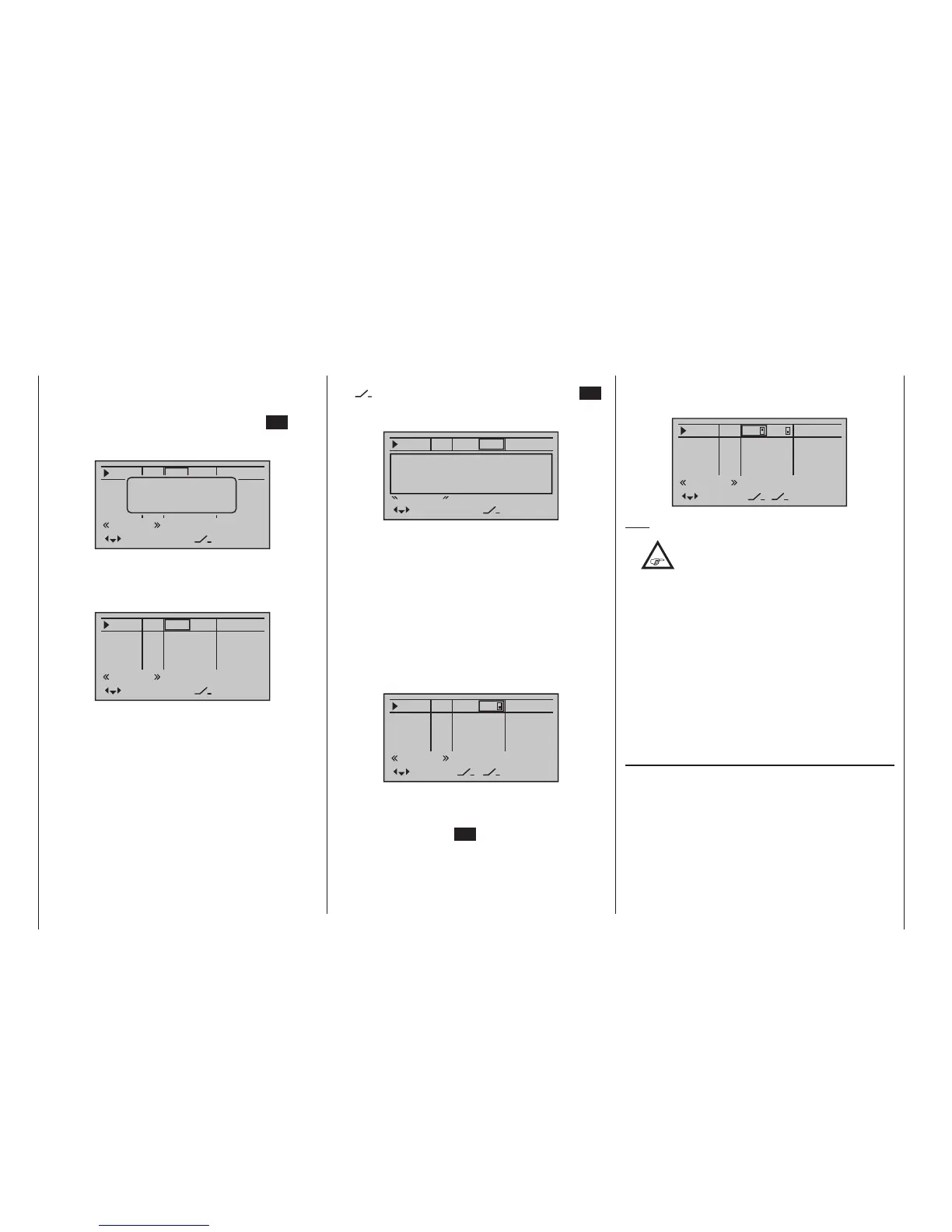
Now put the 3-way switch back into its middle posi-
tion. Move the marker frame as necessary to the left
into the column labelled with the new switch symbol,
briefly tap on the centre SET key of the right four-way
button then assign the switch’s other switch direction
by once again starting from the middle position but this
time move the switch in the other direction.
The display will now present the given switch number
together with a symbol indicating the given switch
direction, for example:
0%
0%
0%
0%
Gyro
In8
–––
–––
–––
GL
GL
GL
GL
normal
fr
fr
3
2
In5
offset
Thro
typ
fr
Tips:
•
When assigning switches, pay attention to
the desired switching direction and also
that all unused inputs remain “free” or are
again reset to “free”. This is necessary to ensure
that inadvertent actuations of these unused con-
trols cannot cause malfunctions.
• The travel setting described below allows the ap-
propriate end state to be established for an as-
signed switch.
Erasing a transmitter control or switch assignment
A simultaneous tap on the or keys of the right
four-way button (CLEAR) while on an input line with
an active transmitter control or switch assignment – see
above figures – will reset the given input back to “fr” and
“---”.
Column 4, “Offset”
The control centre for the given control, i. e. its zero
point, can be changed in this column. The adjustment
range lies between -125 % and +125 %.

 Loading...


