135
Program description - Channel 1 curve | Winged models
Changing reference point values
Move the stick into the range of the reference point
that is to be changed: “L” (low), 1 … 4 or “H” (high).
The number and current curve value of this point are
displayed. Press the central SET button of the right-
hand four-way button to activate the Value field. The
reference point value displayed in inverse video can be
changed in a range of -125 % to +125 % without influ-
encing the neighboring reference points.
Example:
2
+50%
–75%
–75%
normal
off
Input
Output
Point
Ch1 curve
Curve
In this sample screen image, reference point “2” has
been set to -75 %.
Note:
If the stick does not coincide with the exact
reference point, please note that the percent-
age value on the “Output” line always relates
to the current stick position.
Trim point function
Alternatively, jumping through active reference points,
in ascending or descending order, can be done with
the selection keys of the left four-way button. Note
that “active” reference points are those which have
already been set. When a jump is made from one to
another, the point value field for the jump’s destina-
tion reference point in the screen’s Point line will be
displayed in inverse video and its position in the graph
will be marked (L, 1 … max. 4 and H) in inverse video
and with a small triangle. The selection keys on the
right four-way button can then be used to change the
reference point jumped to as described above, entirely
independently of the control position.
2
+50%
–75%
–75%
Trim point
normal
Input
Output
Point
Ch1 curve
One touch on the centre ESC key of the left four-way
button terminates this trim point function.
Trim offset function
When a value field is active, i. e. in inverse video, it is
not only possible, as previously described, to jump to
and change a reference point already set with the
selection keys of the left four-way button but also an
existing curve can be vertically repositioned with the
keys of the left four-way button within a range of
±25 %:
1
0%
+50%
+50%
Trim offset
normal
Input
Output
Point
Ch1 curve
1
0%
0%
0%
Trim offset
normal
Input
Output
Point
Ch1 curve
A tap on the centre ESC key of the left four-way button
will also terminate this function.
Trim x-axis function
This function is activated by tapping the left () or
right () selection key of the right four-way button with
an active (i. e. inverse video) value field. You can then
use the selection keys on the right four-way button to
reposition the active point horizontally or vertically as
you wish:
?
0%
–33%
0%
Trim X-axis
normal
Input
Output
Point
Ch1 curve
Notes:
•
If the point is repositioned horizontally fur-
ther away from the current control position
than approx. ±25 %, a “?” sign will reap-
pear in the line Point. This question mark does not
refer to the repositioned point, however: instead, it
signies that a further point can be set at the cur-
rent control position.
• Please note that the percentage value on the
“Output” line always relates to the current stick po-
sition and not to the position of the point.
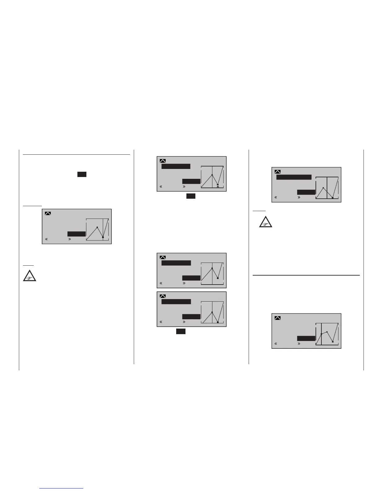
Smoothing the Channel 1 curve
In the example below, sample reference points have
been set:
reference point 1 to 0 %,
reference point 2 to +25 % and
reference point 3 to -75 %
as described in the last section:
1
–50%
0%
0%
normal
off
Input
Output
Point
Ch1 curve
Curve

 Loading...


