153
Program description - Phase settings | Helicopter models
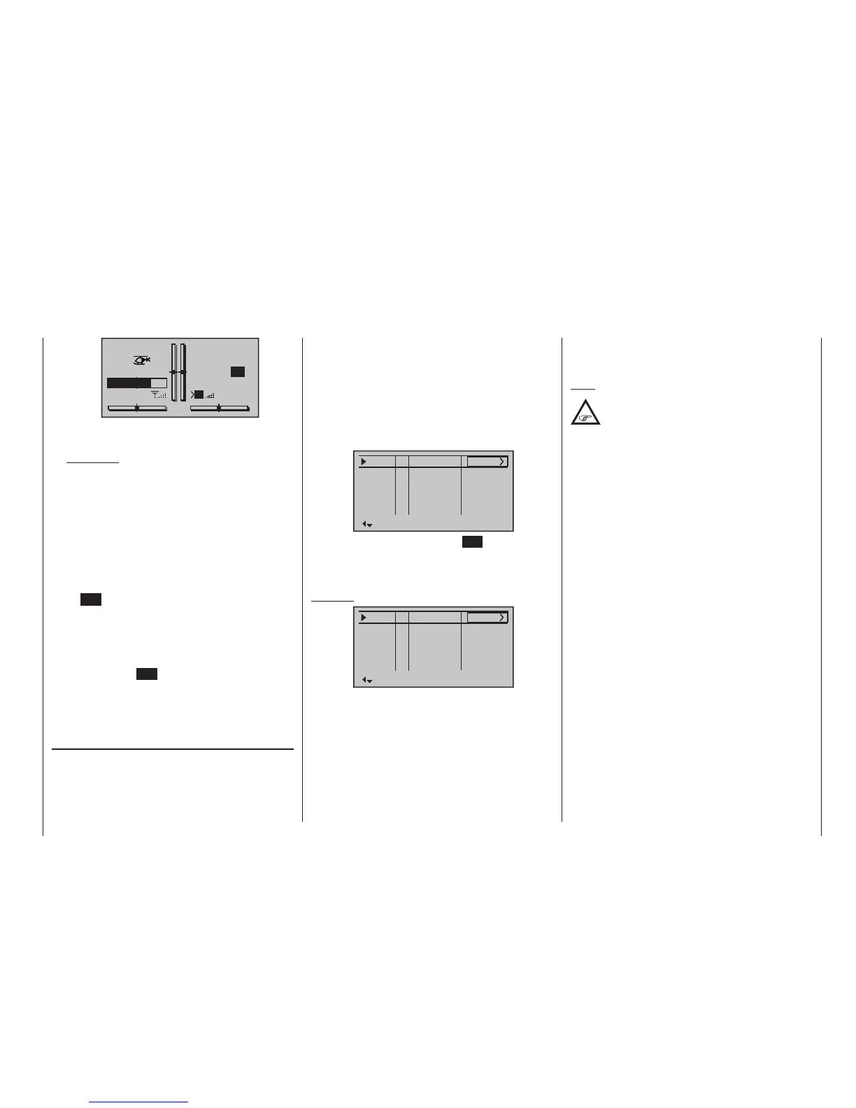
STARLET
#02
2:22h
Stp
Flt
«Speed »
K78
0:00
0:00
5.5V
3.9V
0:00.0
M
Time1
00
When necessary, the selection keys can be used to
access and read the sequence of switching times.
Application:
Measurement of (e. g.) ight phases with in-
creased motor speed, if the same switch is used
to actuate ight phase switching.
• Time2
This timer stores both the “off” and the “on” periods
for the associated switch, i. e. every switch actua-
tion in either direction will cause a record to be writ-
ten for the timer, the timer will be reset then starts
incrementing by “1” again as time passes.
Each time count can be suspended with the cen-
tre ESC key of the right four-way button, without
actuating the switch itself. Activating the switch, in
turn, increments the counter by 1 and restarts the
“Time2” timer.
In order to read out the time memory with the selec-
tion keys, the “Time2” timer must first be suspend-
ed by using the ESC key of the right four-way but-
ton.
A simultaneous tap on the or keys of the right
four-way button (CLEAR) will reset suspended timers
shown in the basic display.
Column “Sw. time”
When you switch between flight phases, it is advisable
to use this column to program a switch time for a “soft”
transition INTO (!) the respective phase. Accordingly,
there is also an option for specifying a different time for
the switchover from any phase to, for example, Phase
3 than for a switchover to Phase 1.
However, for reasons of safety, transition into the auto-
rotation flight phase should ALWAYS be set to switch
without any time delay. The arrow “->” in the column
labelled “Sw.time” at the end of the “Autorot” line indi-
cates that a delay can be set when transitio ning FROM
(!) autorotation INTO (!) another phase.
Use the selection key of the left or right four-way
button to move the marker frame to the right beyond
the “ph.Tim.” column:
Pha1
Pha2
Pha3
Name Sw.time
Pha4
+
+
Normal
Hover
–
–
0.1s
0.1s
0.1s
0.1s
0.1s
Speed
AutorotAuto
Following a brief tap on the centre SET key of the right
four-way button, the switchover time value in the field
displayed in inverse video can be changed within a
range of 0 and 9,9 s.
Example:
Pha1
Pha2
Pha3
Name Sw.time
Pha4
+
+
Normal
Hover
–
–
3.0s
2.0s
5.5s
4.0s
0.1s
Speed
AutorotAuto
A delay of 5,5 s applies when switching FROM auto-
rotation into any other phase. A delay of 0,0 s always
applies when switching TO auto-rotation.
The switchover time from any other phase to Phase 1
«normal» will take 3,0 s.
When switching from e. g. Phase 1 to Phase 3, the
switch time is set to 4,0 s.
Such asymmetric transition times can be useful when,
e. g. switching between extremely different flight phas-
es, such as between aerobatics and normal flight.
A simultaneous tap on the or keys of the right
four-way button (CLEAR) will reset the time in the cur-
rently active value field back to 0,1 s.
Note:
The “switch time” set here applies uniformly
to all settings that are specic to ight phas-
es, and thus to all mixers activated in the
»Helicopter mixer« menu, see page 184. Accord-
ingly, the transition between ight phase-specic
mixers does not occur abruptly. If you want individual
servos to be switched without a delay, however,
dene these accordingly in the »Non-delayed
channels« menu, see page 157, which is available
as standard on the
mc-20 HoTT transmitter only.

 Loading...


