185
Program description - Helicopter mixer
again here in detail using pitch configuration as an ex-
ample, to save you having to leaf through the manual.
In the remaining lines, first activate the value field and
then use the selection keys of the left or right four-way
button to set a mixer value in the value field (inverse
video).
The settings available are rounded off with the “Swash-
plate limiter” option: This option can be set to restrict
maximum deflection of the swashplate servo in the
sense of a limiter. Together, these settings configure the
basic set-up of the helicopter model.
In the “Autorotation” flight phase as described on page
198, however, the mixers “C1 Throttle” and “C1
Tail” are not needed and therefore switched to a config-
urable default value.
Changed parameters can be reset to their respec-
tive default values at any time with a simultaneous tap
on the or keys of the right four-way button
(CLEAR).
Pitch (Pitch curve (C1 Pitch))
If necessary, use the selection keys of the left or
right four-way button to move to the “Pitch” line then
tap briefly on the centre SET key of the right four-way
button:
Input
Output
Point
?
0%
0%
0%
Pitch
normal
Curve
off
Unlike the »Channel 1 curve« menu, this display is
only associated with the control curve of pitch servos,
whereas the “Channel 1 curve” affects all servos con-
trolled by the throttle/pitch stick.
Note that the output signal of the “Chan-
nel 1 curve” option thus functions as an
input signal for the collective pitch curve
programmed here: In the graph, the vertical line is
synchronized with the throttle/collective pitch
stick and therefore follows the current Channel 1
curve characteristic.
The control curve can be defined (separately per flight
phase) by up to 6 points, termed “reference points”,
placed at any point along the stick travel.
Initially, however, fewer reference points are adequate
for setting up the collective pitch curve. We recom-
mend beginning with three reference points to start
with. These three points, namely the two end-points
“Pitch low (L)” (= -100 % control travel) and “Pitch high
(H)” (= +100 % control travel) plus a point at the centre
of control travel still to be set, define an initially linear
profile for the pitch curve.
Programming details
First, switch to your chosen flight phase, e. g. «Nor-
mal».
The throttle/collective pitch stick is used to move the
vertical line in the graph between the two end-points
“Point L” (minimum pitch at -100 %) and “Point H”
(maximum pitch at +100 % control travel): at the same
time, the current stick position is shown numerically on
the “Input” line (-100 % to +100 %).
The point at which the vertical line crosses the curve
is termed the “Output”, and can be varied at the maxi-
mum of 6 reference points within the range -125 % to
+125 %. A control signal modified in this way affects
only the collective pitch servos.
In the example to the left, the stick is at exactly 0 % of
control travel and also generates an output signal of
0 %, since the characteristic curve is linear.
Up to six additional reference points can be set be-
tween the two end-points “L” and “H”, although the
distance between neighboring reference points must
not be less than approx. 25 %.
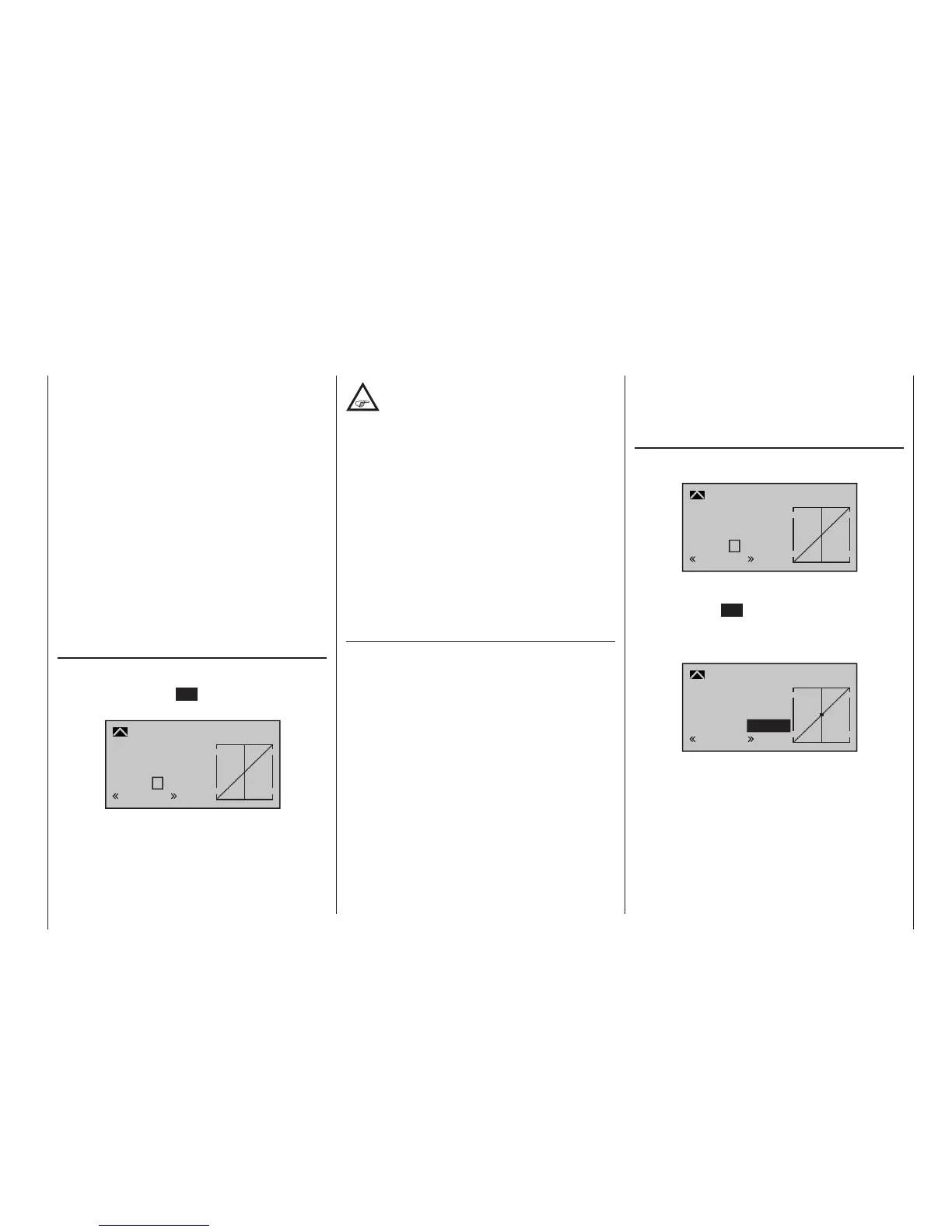
Setting reference points
If necessary, use the left or right-hand arrow button
to move the marker frame down to the “Point” line:
Input
Output
Point
?
0%
0%
0%
Pitch
normal
Curve
off
Move the stick. If the display shows a framed question
mark, then you can set the next reference point with a
tap on the centre SET key of the right four-way button.
Simultaneously, the “?” is replaced by a number and
the value field to the right of the reference point number
is highlighted:
1
0%
0%
Pitch
normal
0%
Input
Output
Point
Curve
off
The order in which up to four reference points are
generated between the end-points “L” and “H” is ir-
relevant since these reference points are continuously
renumbered automatically from left to right as they are
entered.

 Loading...


