196
Program description - Helicopter mixer
maintaining a constant rotational speed.
Climb settings
The combination of throttle hover setting, collective
pitch setting for the hover and the maximum collective
pitch setting (point “H”) now permits, in a simple man-
ner, a means of attaining a constant rotational speed
from hovering right through to maximum climb.
First, perform a prolonged, vertical climb by moving
the collective pitch stick to its end-point. Compared to
the hover configuration, motor speed should remain
unchanged.
If motor speed falls off in the climb, even with the drive
system working at full power and therefore no further
power increase is possible, then reduce maximum
blade pitch angle at full deflection of the collective pitch
stick, i. e. the value of point “H”. Conversely, the attack
angle should be increased if motor speed is to increase
while climbing. Therefore, on the “Pitch” graph page,
put the vertical line on Point “H” by moving the pitch
stick then change this point’s value appropriately with
the selection keys of the right four-way button.
This diagram shows only the
changes when setting the maximum
collective pitch value.
+100%
-100%
OUTPUT
2 3 4 51
Control travel
Hover
point
Then bring the model back to hover, which should, in
turn, be achieved with the C1 stick at its centre point.
If the hover flight point is now achieved only by moving
the pitch stick away from its centre point toward “high-
er” values then this deviation should be compensated
by increasing the hover-flight pitch value – i. e. for point
“1” – a little until the model once again hovers with the
stick at its centre point.
Take great care when configuring these settings, by
adjusting the control linkage as required and/or altering
the linkage point on the servo or carburettor lever. Only
then should the throttle servo’s fine-tuning be electroni-
cally optimized.
Caution:
Inform yourself thoroughly about the
dangers and safety precautions applicable
to handling motors and helicopters before
starting the motor for the rst time!
With this basic set-up complete, the motor should be
started in accordance with the motor operating instruc-
tions: idling can then be configured using the trim lever
of the throttle/collective pitch stick. The preset idle
position will be displayed on the transmitter’s basic
display by a horizontal bar next to the C1 trim lever
position indicator. Refer to the description of digital trim
on page 62 of this manual.
The model should lift off the ground with the collective
pitch stick roughly at its centre point and hover roughly
at the expected rotational speed. If this is not the case,
proceed as follows:
1. The model does not lift off until the collective
pitch stick is above the centre point:
a) Rotational speed is too low
Remedy: On the graph page
for “C1 Throttle” increase
the value for point“1”.
+100%
0%
OUTPUT
2 3 4 51
Control travel
Hover
point
b) Rotational speed is too high
Remedy: Increase the blade
angle of attack pitch by in-
creasing the value of point “1”
on the “Pitch” graph page.
+100%
0%
OUTPUT
2 3 4 51
Control travel
Hover
point
The model lifts off before the centre point is
reached:
a) Rotational speed is too high
Remedy: Decrease the car-
burettor opening by reducing
the value of point “1” on the
graph page for “C1 Throt-
tle”.
+100%
0%
OUTPUT
2 3 4 51
Control travel
Hover
point
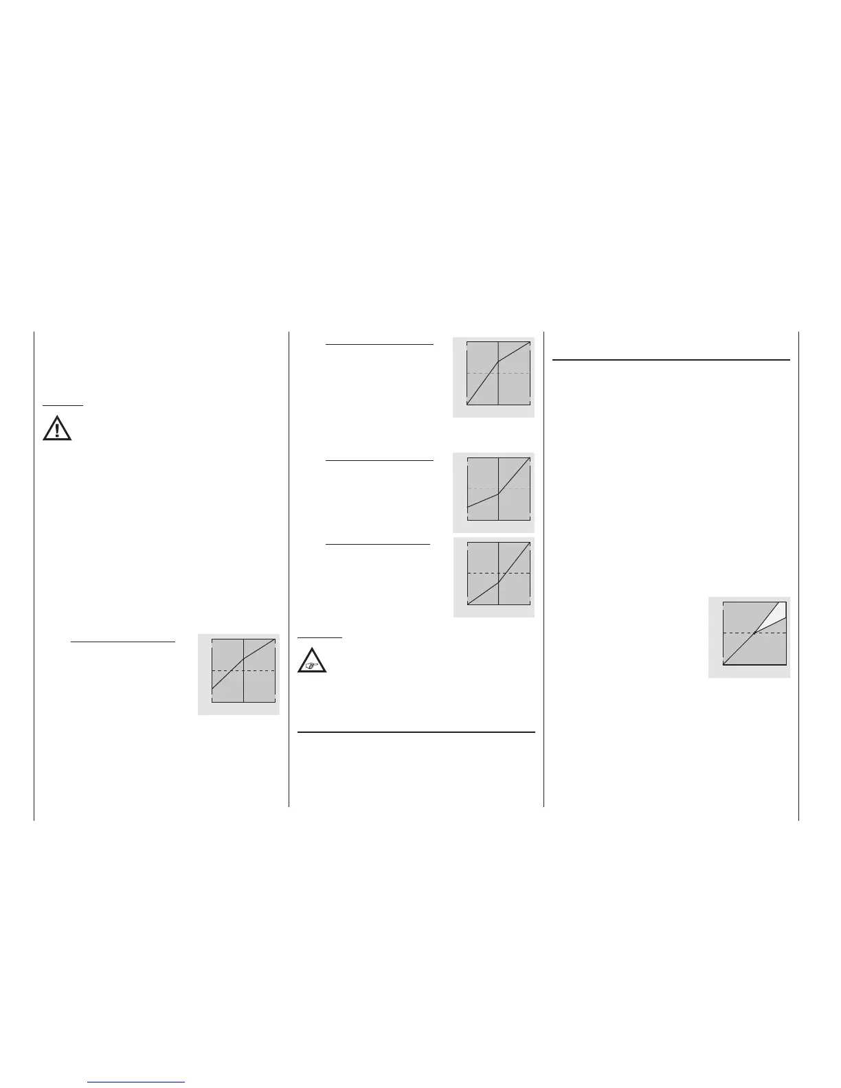
b) Rotational speed is too low
Remedy: Decrease the blade
angle of attack pitch by
reducing the value of point
“1” on the graph page for
“Pitch”.
+100%
0%
OUTPUT
2 3 4 51
Control travel
Hover
point
Important:
These settings must be recongured until the
model hovers at the correct rotational speed
with the throttle/collective pitch stick at its
centre point. The conguration of all other model
parameters depends on these settings being made
correctly!
Standard set-up
Standard set-up is completed on the basis of the basic
set-up described above, whereby the model hovers
in normal flight at the correct rotational speed with the
throttle/collective pitch stick set to its centre point:
This means a set-up with which the model is capable
of both hovering and flying circuits in all phases while

 Loading...


