83
Program description - Base setup models | Winged models
Observe, however, observe the installa-
tion instructions of the relevant module.
The choice of “inverted” instead of the default preset
“normal” allows for appropriate adaptation of the pro-
vided PPM signal.
A simultaneous tap on the or keys of the right
four-way button (CLEAR) will reset the display to “nor-
mal”.
Receiver channel mapping
Note:
This menu line is suppressed in the “Module”
line if you select “EXT.” or “SP.”.
As long as there is at least one “bound” HoTT receiver
in the “Module” line, the next line down will be the “Rcv
Ch map” line:
1
bind
bind
SET
GRAUBELE
SET
Rcv Ch Map R12
R08
HoTT
Mod.name
Stick mode
module
Base setup model
As already mentioned in the introduction to the sec-
tion entitled “Binding receivers”, mc-16 HoTT and
mc-20 HoTT transmitters feature a menu point in
which the transmitter’s control channels can be re-
distributed in any way you like within one receiver, and
also include an option to distribute the transmitter’s
control channels to a maximum of two receivers in any
arrangement you desire. These are the eight control
channels of the mc-16 HoTT transmitter, and the
twelve control channels of the mc-2 0 HoTT. This re-
distribution is termed “mapping” or “channel mapping”
(channel assignment) in the following section.
Select the receiver to be “mapped” with the selection
keys of the left or right four-way button then tap briefl y
on the centre SET key of the right four-way button.
Channel mapping within a receiver
This menu point provides a simple means of re-map-
ping the transmitter’s control channels in any way you
like, in a similar manner to the channel assignment
function termed “Channel mapping” in the »Tele-
metry« menu, as described on page 241. This means
that you can re-distribute the transmitter’s control
channels, which are present at the receiver inputs, to
the selected receiver’s outputs / servo sockets in any
way you like:
Receiver CH – BIND1
In Ch
In Ch
In Ch
In Ch
1
2
3
4
1
2
3
4
Out Ch
Out Ch
Out Ch
Out Ch
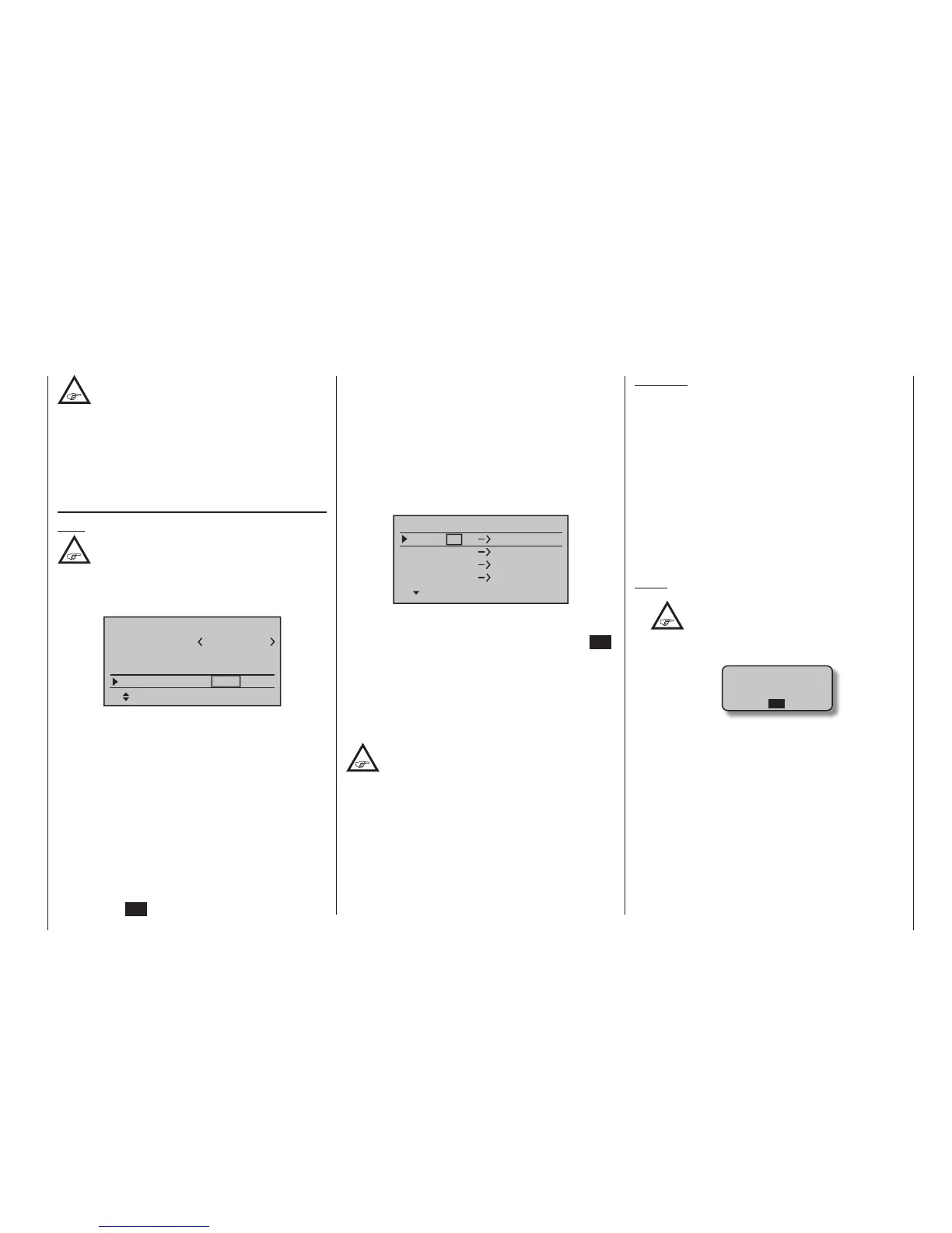
After selection of the desired output with the selection
keys of the left or right four-way button, the appropriate
value fi eld will be framed. Briefl y tap on the centre SET
key of the right four-way button. The current setting will
be displayed in inverse video. Now use the selection
keys of the right four-way button to select the desired
input channel’s respective transmitter output, see page
226.
BUT CAUTION:
If, for example, “2AIL” has been specifi ed in the
“Aileron/camber fl aps” line of the »Model
type« menu then the transmitter will have
allocated control function 2 (ailerons) to control chan-
nels 2 & 5 for the left and right ailerons. The corre-
sponding receiver inputs to be assigned in this case
would be channels 2 & 5, refer to the example below.
Examples:
• You would like to control each aileron of a large
model with two or more servos.
Assign each of the appropriate outputs (servo con-
nections) to one and the same input (control chan-
nel). In this case, depending on left or right wing,
as the respective input to one of the two default ai-
leron control channels (2 or 5).
• You would like to control the rudder of a large
model with two or more servos.
Assign each of the appropriate outputs (servo con-
nections) to one and the same input (control chan-
nel). In this case, the default rudder channel (4),
see gure right.
Notes:
•
The maximum number of lines (outputs)
available corresponds to the maximum
number of servos which can be connected
to the receiver in question.
• If you see the warning …
CAN‘T
RECEIVE
DATA
OK
… then there is no bound receiver within range.
If the case may be, switch the RF module or/and
your receiving system on.
• With the »Tx. output swap« option, which is
available only on the
mc-20 transmitter, see
page 226, the transmitter’s control functions can
be interchanged in any way; it is also possible to
assign multiple outputs to one and the same con-
trol function. In the interests of clarity however we
strongly advise that you use only one of these two
options.

 Loading...


