100
Installation
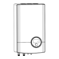
Location of Refrigerant and Water Pipeline are shown
below.
8.2.8.2
REFRIGERANT PIPING CONNECTION
Piping connection size of indoor unit is shown below.
Model Gas pipe Liquid pipe
044(2.0HP)
Ø 12.7 (1/2)
Ø 6.35 (1/4)060(2.5HP)
080(3.0HP) Ø 15.88 (5/8)
Torque required is shown below.
Pipe Diameter Torque(N•m)
Ø 6.35 14~18
Ø 9.53 33~42
Ø 12.7 49~61
Ø 15.88 63~77
Screw up the nut cap by two wrenches. Heat preservation material
on site should be used to prevent heat leakage of gas pipe, liquid
pipe and connecting nut cap.
Unit: mm
61
115
84
84
84
84
75
174
8.2.8.3
WATER PIPING CONNECTION
Piping connection size of indoor unit.
Model
Space
heating/
cooling
water inlet
DHW Outlet
(Hot Water)
DHW Inlet
(Cold Water)
Space
heating/
cooling water
outlet
044(2.0HP)
G1
(female)
G3/4
(female)
G3/4
(female)
G1
(female)
060(2.5HP)
080(3.0HP)
Torque
Required
40~50(N•m)
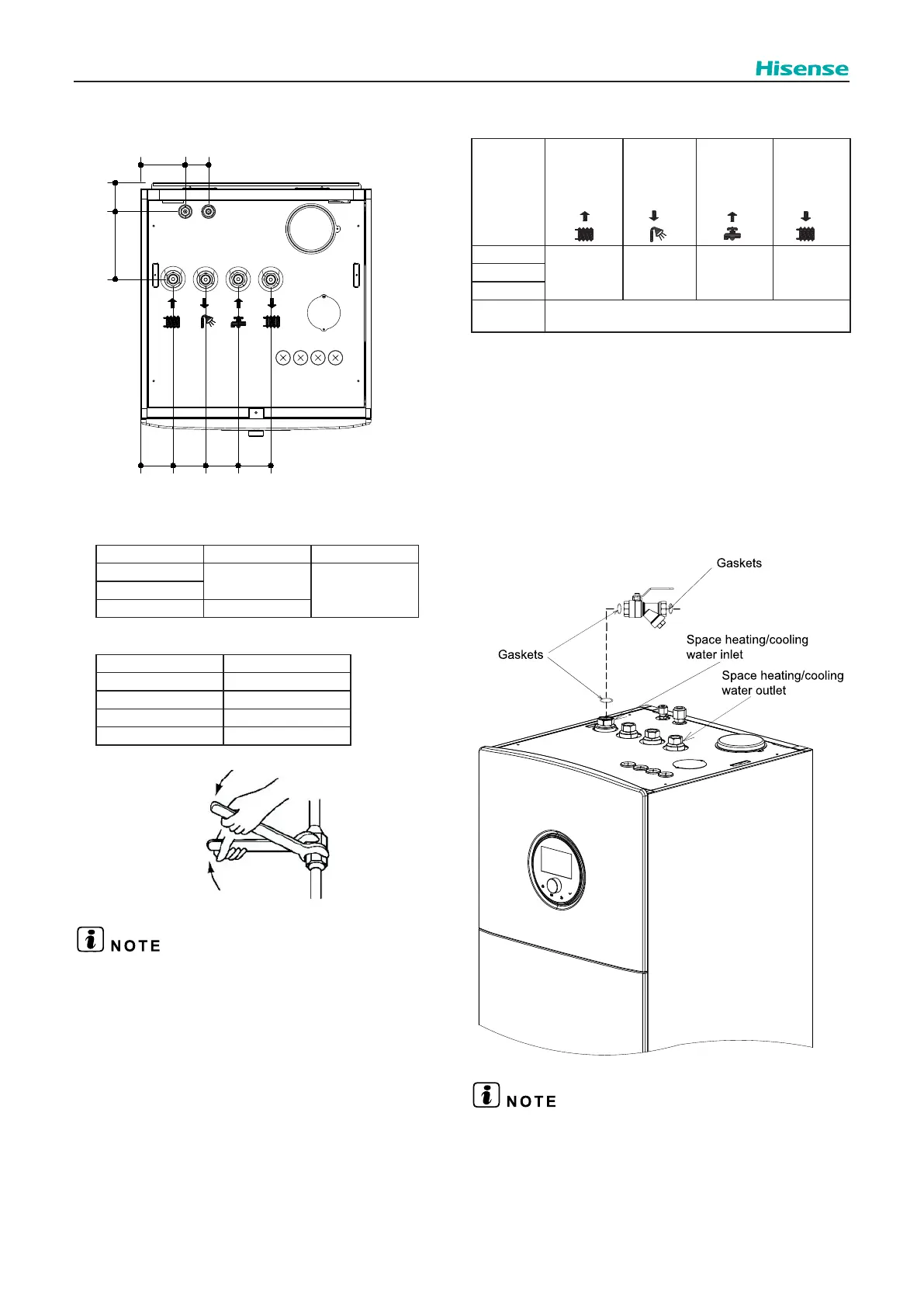
8.2.8.3.1 Space heating/cooling pipes connection
(1)
convenience of repair and maintenance, install the
as follows. The space heating/cooling installation can
be carried out referring to section 9.1.
 Loading...