393
Troubleshooting
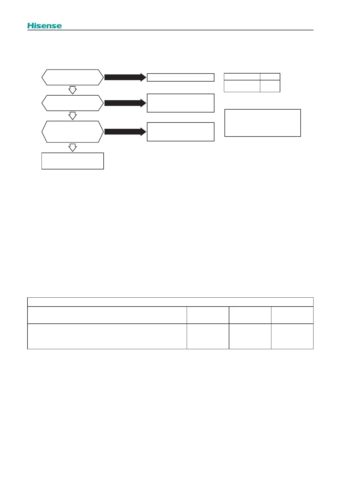
1.3.4 Checking of Reversing Valve
If outdoor unit does not start the heating operation or defrosting operation, there may be a malfunction of the reversing valve.
The troubleshooting is indicated below.
Is the connector PCN6
*1) on O.U. main PCB
connected correctly?
Yes
Connect it correctly.
Connector No. Pin No.
Note:
Reversing Valve signal as following
Heating- OFF
Cooling- ON
PCN6
(O.U. main PCB)
1 to 2
*1)
No
Is the resistance of
the reversing valve coil
correct?
Reversing valve is faulty
(disconnection, etc.).
Replace it with a new one.
No
No
Yes
Yes
Is there output voltage
generated from the
connector PCN6 *1)
on O.U. main PCB?
O.U. main PCB is faulty (Faulty
reversing valve circuit, etc.).
Replace it with a new one.
Reversing valve is faulty
(valve locking, etc.).
Replace it with a new one.
1.3.5 Checking of DC Fan motor
When O.U. main PCB is faulty and Alarm 57 appears, the fan motor may also be damaged. To prevent O.U. main PCB
damage which may result from operation combined with a faulty fan motor, check also if the fan motor is not damaged when
O.U. main PCB is replaced.
Procedure in case of error diagnosis.
(1) Remove fan motor connectors for DC fan motor from the O.U. main PCB(CN14) and turn the fan motor shaft by hand.
Normal
: The fan motor shaft turns smoothly.
Faulty
: No continuous rotary torque movement felt when turning the motor by hand. This occurs because the internal
magnet of the fan motor breaks the movement when the internal electronic circuit of the fan motor has a short-circuit fault.
(2) Measure the fan motor resistance:
a . Disconnect the connector of DC fan motor from O.U. main PCB.
b . Connect the black test lead wire to the pin terminal of black wiring for the connector of DC fan motor.
c . Connect the red test lead wire to each measuring pin terminal for the connector of DC fan motor.
Wiring Color for Measurement (Normal Value)
Red-Black
White-
Black
Yellow-
Black
Blue-
Black
2.6MΩ or greater
about
28kΩ
about
188kΩ
25MΩ
or
greater
NOTE:
If the wires are connected other way around the resistance can not be measured correctly.
It is normal when the resistance is the same or closed as the normal values in the table up.
It is abnormal if the resistance is completely dierent from the normal values in the table up.
(Open fault: innity; Short-circuit fault: several Ω to several kΩ)
The condition of open fault and short-circuit fault in the electronic circuit of DC fan motor can be checked if the value shows
abnormality.
 Loading...