460
Hi-Therma Monobloc System (AHZ-044/080HCDS1)
2.4.7.3
Replacing O.U. main PCB
Remove the Upper cover, as explained in”2.3.1.1 Removing the Upper cover”
Remove the Service cover, as explained in”2.3.1.2 Removing the Service cover”
Remove the electrical box cover, as explained in “2.3.1.3 Removing the electrical box cover on indoor part”
Remove the front cover, as explained in “2.3.1.4 Removing the front cover”
Remove the electrical box assembly, as explained in “2.3.7.2 Removing the Electrical Box Assembly on Outdoor Part”
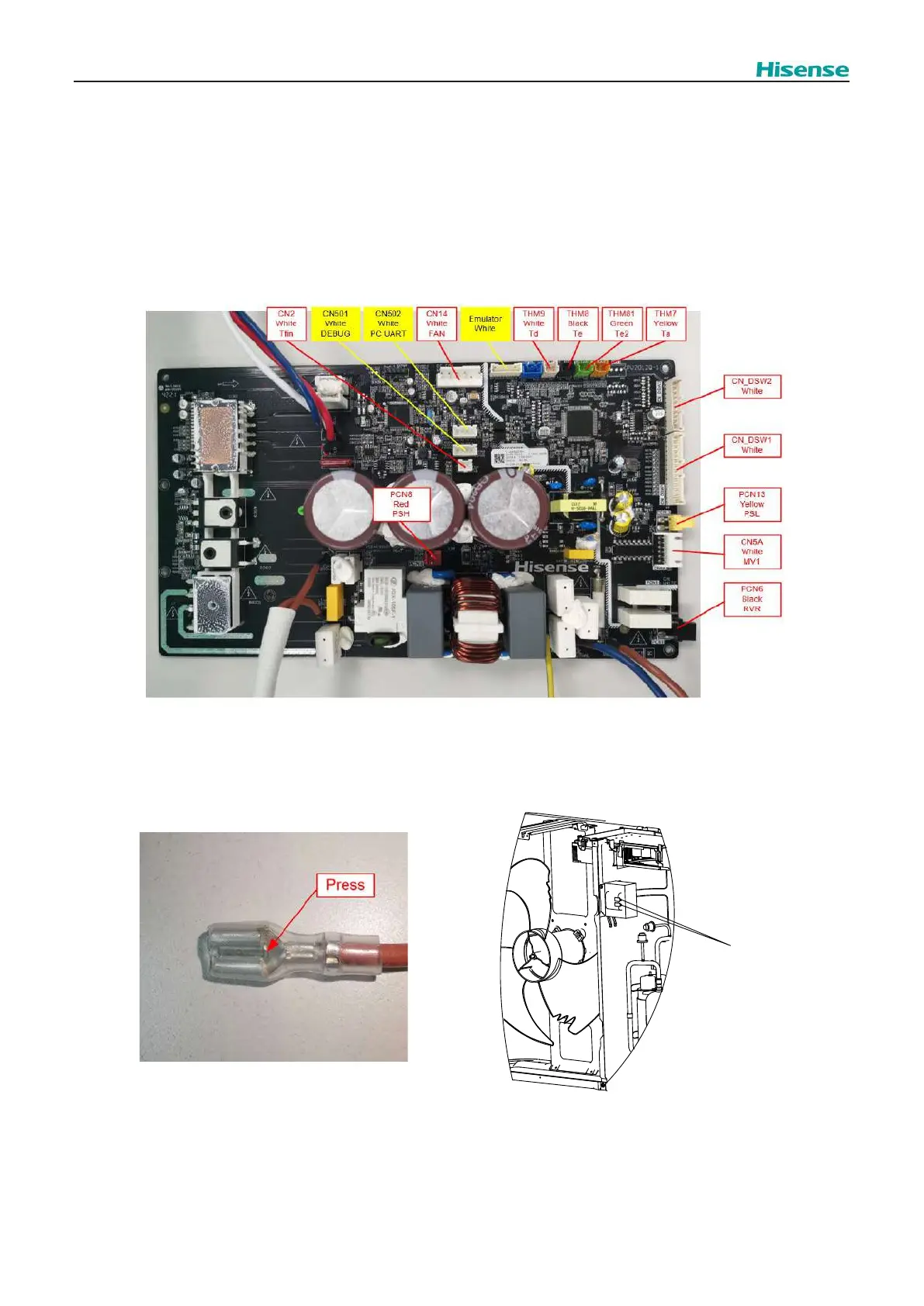
Remove all terminals from the O.U. main PCB and disconnect the PFC inductor terminals, compressor terminals, the input
power cable, and the earth terminals.
All terminals are located as shown below, and the terminals which need to be inserted and disconnected during the
replacement are marked in red.
Note: When removing the PFC inductor terminals, the wiring harness terminals have their own latches which can be removed
after pressing the pick on the terminals. Do not pull out forcibly, otherwise it may cause damages to the PFC inductor terminal.
Fig.2.21 for the location of the screws) of the PCB, then the PCB and Fin are separated
from electrical box.
Fig.2.19 O.U. main PCB
Fig.2.20 PFC inductor
PFC
inductor